1. General Introduction (1.0MB):
2. The Model M-125-MN Fialka (2.5MB):
3. The Much More Complex M-125-3MN/-3MP3 Fialka (2.5MB):
4. Disassembly of the Much More Complex M-125-3MN/-3MP3 Fialka (8.5MB):
5. Rotor Descriptions, Wiring and Stepping Data (This page)(1MB):
6. The 24 Volt Fialka Power Supplies (0.4MB):
7. The Accessories and the Cover (0.8MB):
8. Fialka Manual: German Language Version (3MB Adobe .pdf file):
9. Fialka Manual: German Language Version (.jpg files):
(Fialka Manual courtesy of collector John Alexander.)
(Download sizes are approximate.)
Fialka Rotor Set Descriptions and Photographs and Rotor Wiring and
Rotation Data:
Fialka Overview:
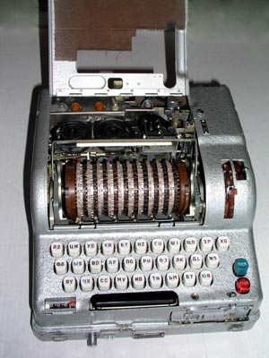
The Russian Fialka Cipher Machine was used during the Cold War era and
manufactured in two versions: The M-125-MN and the more complex
M-125-3MN/-3MP3.
The Fialka is a 10 rotor cipher machine that is similar in basic design to the
German WW-2 Enigma, the Swiss NEMA, and other multiple-rotor cipher machines.
It does, however, differ from other cipher machines in several very
significant ways. The Fialka itself is described in much more detail in other
sections where you will also find a digitized German language version of its
instruction manual. This page deals exclusively with the ROTORS.
Differences Between the Fialka Rotors and Those of Other Cipher
Machines:
Rotor Rotation Direction:
The Fialka rotates each of its 10 rotors in a direction that is opposite to
that of each neighboring rotor. Most other cipher machines have rotors that
all turn in the same direction. The rotor advance blocking pins that control
the rotation of individual rotors are described and the locations of all pins
for all rotors are given in tables below along with sample rotation data.
Unique Rotors:
The Fialka can use either a simple, non-adjustable set of rotors or an
extremely unique and complex set of multi-adjustable modular-wiring-matrix
rotors that allow a very large number of internal wiring variations. These
simple and complex rotor sets are described in detail below and their internal
wiring data is presented in comprehensive tables.
DETAILED DESCRIPTIONS OF THE ROTORS AND ROTOR WIRING:
The Rotors and data are so complex that a Menu will be used to help in finding the appropriate information:
ROTOR MENU:
-
1. General Overview of The Rotor Series, Rotor Sets and Rotor types:
-
2. Descriptions and Photographs of the Non-Adjustable Rotor Sets.
-
3. Wiring Data for the Non-Adjustable Rotor Sets.
-
4. Rotor Advance Data for the Non-Adjustable Rotor Sets.
-
5. Descriptions and Photographs of the Multi-Adjustable Removable-Wiring-Maze
Rotor Sets.
-
6. Adjusting the Multi-Adjustable Removable-Wiring-Maze
Rotor Sets.
-
7. Wiring Data for the Multi-Adjustable Removable-Wiring-Maze
Rotor Sets.
-
8. Rotor Advance Data for the Multi-Adjustable Removable-Wiring-Maze
Rotor Sets.
ROTOR OVERVIEW:
Rotor SERIES:
Two different SERIES of rotors are known to exist. Each of the rotors in
these two SERIES has entirely unique wiring and stepping data. The wiring and
stepping data for both of these SERIES is presented below:
The "3K" SERIES:
Every Rotor in this SERIES has a "3K" imprinted into its input side. This
SERIES contains both Non-Adjustable and Multi-Adjustable Removable-Wiring-Maze
Sets of rotors. At least some of these "3K" SERIES rotors are known to have
come from Poland.
The "6K" SERIES:
Every Rotor in this SERIES has a "6K" imprinted into its input side.
This SERIES contains both Non-Adjustable and Multi-Adjustable Removable-
Wiring-Maze Sets of rotors. At least some of these "6K" SERIES rotors are
known to have come from the former Czechoslovakia.
General Conclusions about Rotor SERIES:
Since each of the unique SERIES above came from a different country, it is
possible that the machines in each country used their own unique SERIES of
rotors. It is also possible that the unique rotor SERIES were used by
different military organizations. It will be interesting to see whether other
SERIES of Fialka rotors are discovered.
Rotor SETS:
A rotor SET contains one rotor for each of the first 10 letters in the
Russian Alphabet. The rotors in a SET are labeled A (the first letter)
through K (the tenth letter).
There are two different SETS of 10-rotors that fit into the Fialka.
Non-Adjustable Rotor SET:
The rotors in one SET are very simple and they are non-adjustable. Each rotor
has a fixed wiring maze connecting the 30 input connections to the 30 output
connections. This non-adjustable SET will be described first in the pages
below.
Multi-Adjustable Removable-Modular-Wiring-Maze Rotor SET:
This set consists of 10 rotors that are identified by the first
10 letters of the Russian Cyrillic Alphabet.
This set contains rotors in the "3K" Series as you will see from the
photographs. Each rotor is imprinted with "3K".
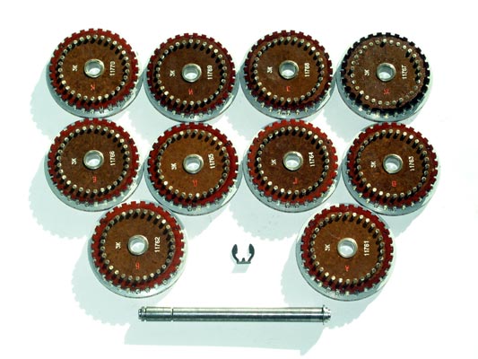
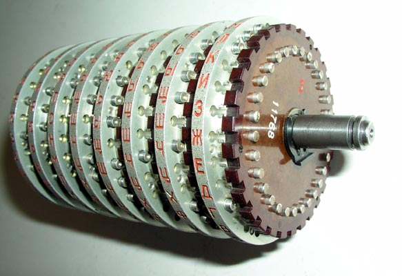
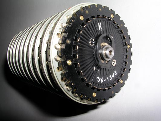
The 10 rotor stack of non-adjustable rotors is shown here after
removal from the Fialka.
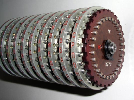
The 10 rotor stack of non-adjustable rotors showing the 30 spring loaded
input contacts and the retaining clip that keeps the rotors on the shaft.
NOTE:
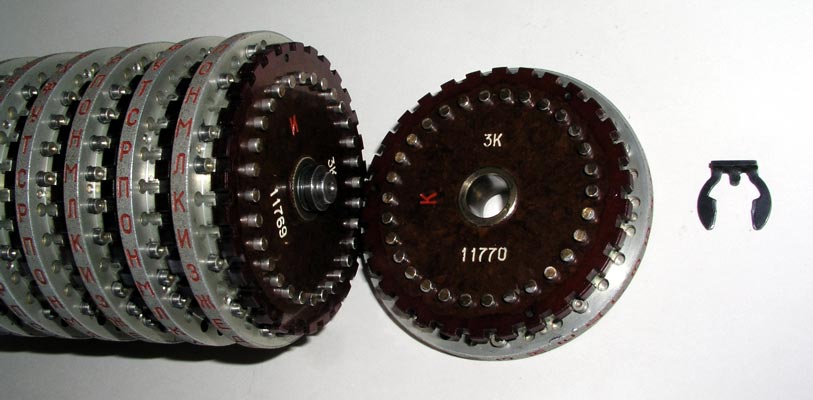
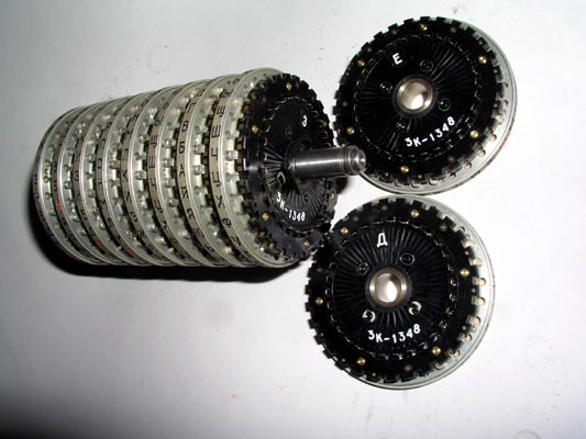
The 10 rotor stack with the retaining clip removed and rotor "K" slid
off the shaft.
The 10 rotor stack with all but rotor "A" removed from the shaft.
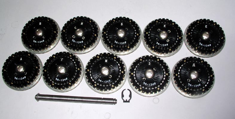
The input contact (right) sides of all 10 non-adjustable rotors after
removal from the shaft.
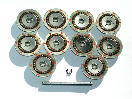
The output contact (left) side of a non-adjustable rotor on the shaft.
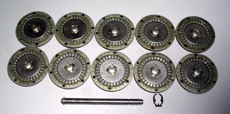
The output contact sides of all 10 non-adjustable rotors after removal from
the shaft.
The shaft with the retaining clip in place to allow 8 rotors to be used
instead of 10. A special filler with contacts on both sides is used to fill
in the remaining space.
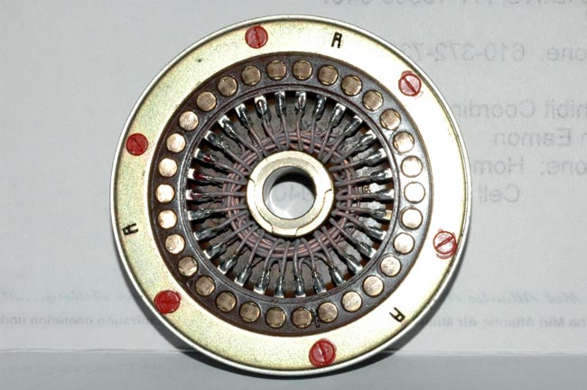
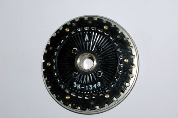
Input Contacts:
The Thirty Input Contacts for the Non-Adjustable Rotor "A". The heavy
lubricating grease lubricates the contacts and eases rotation.
Output Contacts:
The Thirty Output Contacts for the Non-Adjustable Rotor "A".
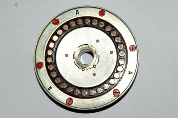
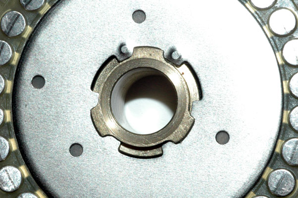
The non-adjustable rotors can be disassembled to allow access to the wiring
maze but no changes can be made to the maze. To access the wiring, this metal
disc is rotated until it releases the brass central shaft as shown in the next
photograph.
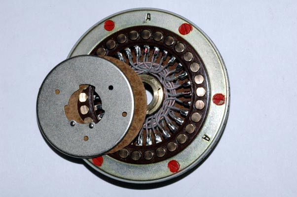
The metal disc and the insulating fiber washer have been moved aside to
reveal the hand-wired wiring maze. Access to the wiring maze makes it easier
to repair any cold-soldered joints.
The complete wiring maze is shown in this photograph.
Here is a closer view of the wiring maze.
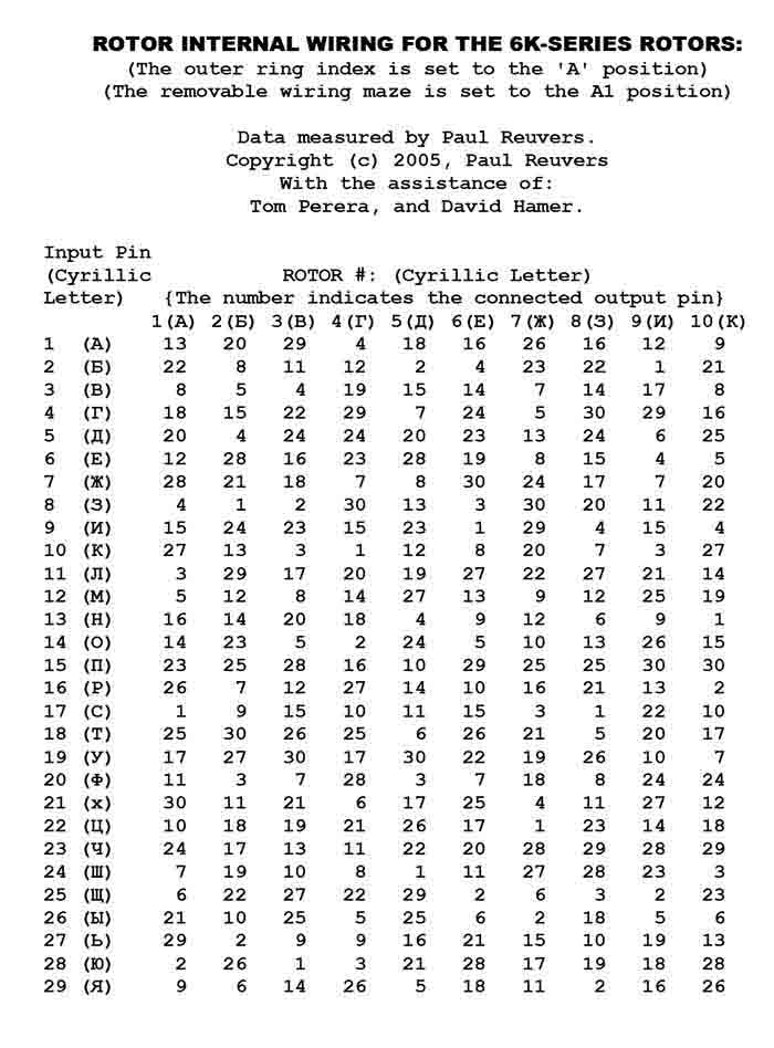
Specific Wiring Data for all Non-Adjustable Rotors in SERIES "3K":
The 30 wired connections between the 30 input contacts and the 30 output
contacts are fixed and can not be changed. The Cyrillic letter stamped on
the outer ring and associated with each contact is also fixed and can not be
changed. The exact wiring between the 30 input and output connections is
given for each of the 10 rotors in a table below. This table shows the
Cyrillic and the corresponding numerical identifier for each of the 30 INPUT
contacts in a column on the left side of the table. The OUTPUT contact that
is fixed-wired to each of the input contacts is given by the number in the
table under the Cyrillic letter identifying each of the 10 rotors. To convert
this number back into its corresponding Cyrillic letter, just use the column
on the left.
**SPECIAL NOTE: The column on the far right side of the table shows the
output contacts that are connected to the 30 input contacts of MULTI-
ADJUSTABLE ROTOR "K" WHEN THE REMOVABLE MODULAR WIRING MAZE HAS BEEN REMOVED
AND REVERSED SO THAT SIDE "2" FACES OUTWARDS AND THE INDEX MARK POINTS TO THE
CYRILLIC LETTER "A". For a further description of this setting, please see
the information on the Multi-Adjustable rotors below:
Specific Advance Data for all Non-Adjustable Rotors in SERIES "3K":
Rotor Rotation Advance Blocking Pins:
Specific Advance Data for all Non-Adjustable AND Multi-Adjustable
Rotors in SERIES "3K" is given below:
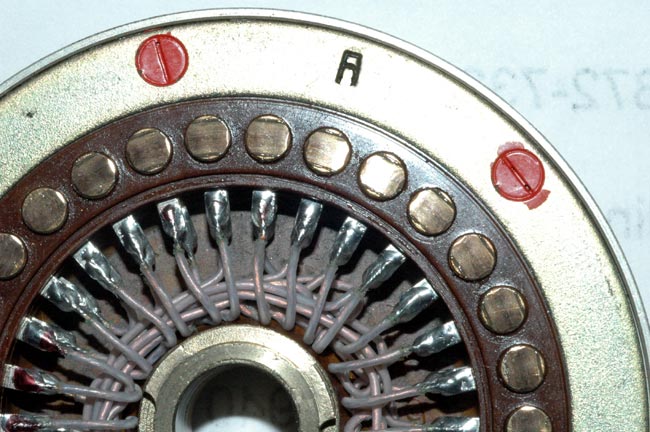
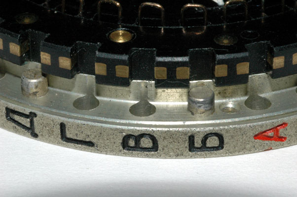
The actual rotation of the rotors is controlled by the placement of the metal
pins adjacent to each of the contacts. These pins block or lock-out the
drive mechanism and determine which rotors will not rotate. This photograph
shows several of the pins and several of the un-pinned locations. A detailed
table showing the locations of all of the pins in all of the rotors may be
found below.
Although all known Fialka rotors have exactly the same rotor advance blocking
pin placements it is possible, with a considerable amount of effort, to
change the placements. These pins can be removed from the rotors and inserted
into other holes but it is quite difficult to do this. It does not appear
to be a real adjustment of the rotor but rather an assembly convenience and
perhaps a provision for a major engineering revision. To remove the pins, the
6 screws holding the outer ring plate must be unscrewed. Each screw is
covered with red paint that both makes it difficult to unscrew, and also
reveals any attempts to do so. After the outer ring plate is removed, the
pins drop out of their cylindrical holes and can be repositioned. This is so
difficult and complex that for field and operational use, it can safely be
assumed that these pins are always to be found in the positions shown in the
table.
This is a close view of the rotation advance blocking pins
for one of the rotors:
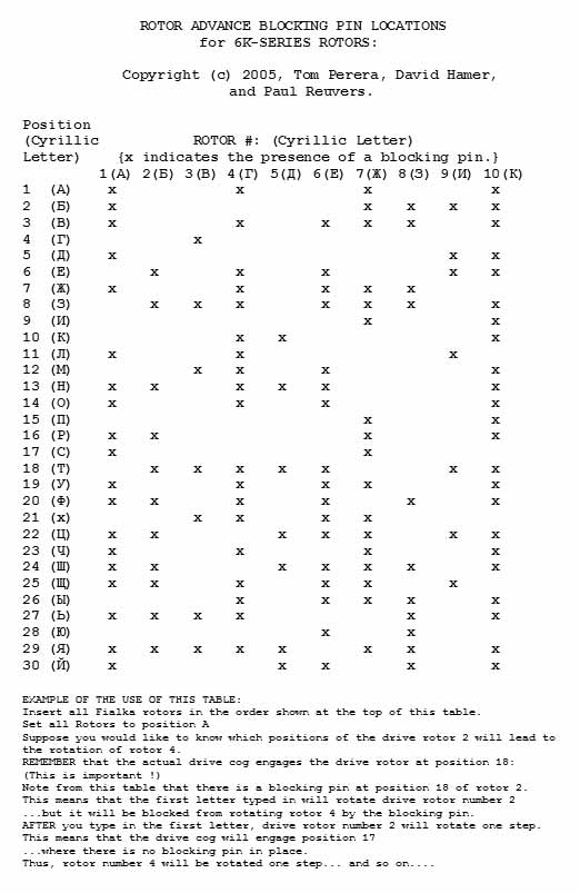
Table showing and explaining the rotation advance blocking pin locations
for all 10 rotors:
This table gives the locations of the advance blocking pins for the Non-
Adjustable and Multi-Adjustable Fialka Rotors of series "3K".
The advance blocking pins (marked with an "x" for each rotor in the table) are
located at the position identified by the Cyrillic letter and contact number
shown in the column on the left. EXAMPLE: For rotor "A" there is no rotor
advance blocking pin in position 1 which is marked with the Cyrillic letter
"A". There is, however, a blocking pin located at position 2.
Please note that this table only gives the actual physical location of the
advance blocking pins. The rotor advance sequence is as shown but the actual
point of advance is different from these locations. The actual position where
the cogs engage and drive the rotors is described below:
Please also note that the Non-Adjustable and Multi-Adjustable rotors are
identical ONLY when the multi-adjustable rotors are set to their overall
'BASE' setting. In the overall BASE setting, the outer lettered ring is set so
that the Cyrillic letter "A" is Adjacent to the Cyrillic letter "A" on the
main rotor frame. Then the internal modular wiring maze is removed and placed
back into the rotor so that its index mark points to the Cyrillic letter "A"
and so that its side "1" is facing outward. Please see the accompanying text
for an explanation of the special multi-adjustable modular-wiring-maze
rotors.
Rotors 2, 4, 6, 8 & 10 (reading from left-to-right)
The actual advancing of rotors 2, 4, 6, 8 & 10 is activated by a drive cog
that engages the rotor at position 18 (When the rotor is set to the "A"
position). An advance blocking pin in the rotor in this position (position
18) will block the rotation of any of these even-numbered rotors to the RIGHT
of that rotor. As the rotors rotate, the place that the advancing cog engages
the rotor changes accordingly.
Rotors 2, 4, 6, 8 & 10 Rotate their upper letters AWAY from the keyboard.
Their rotation is driven by rotor 2 which drives rotors 4, 6, 8 & 10 in that
order. For these 5 rotors, ANY Rotor Advance Blocking Pins existing in the
drive slot of a rotor to the LEFT of a given rotor will prevent it from
rotating. In other words, a Rotor Advance Blocking Pin blocks the rotation of
any of these 5 rotors to the RIGHT of the rotor that has the pin. Rotor
Advance Blocking Pin locations are given in an accompanying table.
Rotors 1, 3, 5, 7 & 9 (reading from left-to-right)
The actual advancing of rotors 1, 3, 5, 7 & 9 is activated by a drive cog that
engages the rotor at position 21 (When the rotor is set to the "A" position).
An advance blocking pin in the rotor in this position (position 21) will block
the rotation of any of these odd-numbered rotors to the LEFT of that rotor.
As the rotors rotate, the place that the advancing cog engages the rotor
changes accordingly.
Rotors 9, 7, 5, 3 & 1 Rotate their upper letters TOWARD the keyboard. Their
rotation is driven by rotor 9 which drives rotors 7, 5, 3 & 1 in that order.
For these 5 rotors, ANY Rotor Advance Blocking Pins existing in the drive slot
of a rotor to the RIGHT of a given rotor will prevent it from rotating. In
other words, a Rotor Advance Blocking Pin blocks the rotation of any of these
5 rotors to the LEFT of the rotor that has the pin. Rotor Advance Blocking
Pin locations are given in an accompanying table.
Sample Rotor Rotation Data:
This table gives sample rotor advancing data for the first 20 letters typed
into a Fialka for all 10 rotors after the rotors have been set to starting
position: A A A A A A A A A A. This table applies to both the Non-Adjustable
and Multi-Adjustable rotors when the Multi-Adjustable rotors are set to their
BASE ring setting. (This BASE setting of the multi-adjustable rotors has all
Cyrillic letter "A"s on the outer ring set Adjacent to the Cyrillic letter
"A"s on the inner ring of the rotor). The table has been constructed in the
following way:
First, each of the 10 rotors was inserted into the Fialka as shown at the very
top of the table with rotor "A (1)" on the far left and rotor "K (10)" on the
far right. (The rotors have been given numbers for convenience in
understanding the paragraphs in the next section:)
Then All 10 rotors were manually rotated to position "A". (The state in which
all rotors are set to position "A" is shown in the table as 1, 1, 1, 1, 1, 1,
1, 1, 1, 1 in the top row of the table.
Finally, 20 letters were typed into the Fialka. Each letter caused some of
the rotors to rotate. The position that each of the 10 rotors had reached
after each letter was entered is shown in the table by a number that
corresponds to a Cyrillic Letter on the outer ring of the rotor.
These numbers may be converted into their Cyrillic letter equivalents by using
the column on the right side of the table which is just placed there as a
convenience in making the conversions.
Rotors 2, 4, 6, 8 & 10 (reading from left-to-right)
Rotors 2, 4, 6, 8 & 10 Rotate their upper letters AWAY from the keyboard.
Their rotation is driven by rotor 2 which drives rotors 4, 6, 8 & 10 in that
order. For these 5 rotors, ANY Rotor Advance Blocking Pins existing in the
drive slot of a rotor to the LEFT of a given rotor will prevent it from
rotating. In other words, a Rotor Advance Blocking Pin blocks the rotation of
any of these 5 rotors to the RIGHT of the rotor that has the pin. Rotor
Advance Blocking Pin locations are given in an accompanying table.
The actual advancing of rotors 2, 4, 6, 8 & 10 is activated by a drive cog
that engages the rotor at position 18 (When the rotor is set to the "A"
position). An advance blocking pin in the rotor in this position (position
18) will block the rotation of any of these even-numbered rotors to the RIGHT
of that rotor. As the rotors rotate, the place that the advancing cog engages
the rotor changes accordingly.
Rotors 1, 3, 5, 7 & 9 (reading from left-to-right)
Rotors 9, 7, 5, 3 & 1 Rotate their upper letters TOWARD the keyboard. Their
rotation is driven by rotor 9 which drives rotors 7, 5, 3 & 1 in that order.
For these 5 rotors, ANY Rotor Advance Blocking Pins existing in the drive slot
of a rotor to the RIGHT of a given rotor will prevent it from rotating. In
other words, a Rotor Advance Blocking Pin blocks the rotation of any of these
5 rotors to the LEFT of the rotor that has the pin. Rotor Advance Blocking
Pin locations are given in an accompanying table.
The actual advancing of rotors 1, 3, 5, 7 & 9 is activated by a drive cog that
engages the rotor at position 21 (When the rotor is set to the "A" position).
An advance blocking pin in the rotor in this position (position 21) will block
the rotation of any of these odd-numbered rotors to the LEFT of that rotor.
As the rotors rotate, the place that the advancing cog engages the rotor
changes accordingly.
Suppose you insert all Fialka rotors such that the rotors are in the order
shown at the top of the table.
Suppose you set all Fialka rotors to the letter "A" position.
Suppose you would like to predict the rotation of rotor 4 as you type in 5
letters.
1. Remember that the drive cog for rotors 2, 4, 6, 8 & 10 is located at
position 18 (Very Important).
2. Look at the table that shows the locations of the rotor advance blocking
pins.
3. Note that there is an advance blocking pin in location 18.
4. This means that when you type in the first letter, the drive wheel "2"
will rotate but the advance blocking pin will prevent rotor "4"
from being turned.
5. You will see in this table that rotor "4" does not rotate as the first
letter is typed.
6. Now type in another letter. The drive rotor, number "2" has moved so that
the drive cog engages position 17 and the table shows that position 17 has an
advance blocking pin in place preventing rotor 4 from turning.
7. Typing in two more letters advances the drive rotor "2" 2 more positions
but rotor advance blocking pins are in place in positions 16 and 15 so rotor 4
still does not turn.
8. Now, type in another letter. The drive cog now turns the drive rotor at
position 14 where there is NO rotor advance blocking pin. Without a drive
advance blocking pin in place, rotor "4" is also rotated and turns to position
30. (This means that the drive advancing cog is now located at position 17.)
Since the table shows that rotor 4 has a drive blocking pin in position 17, it
does not allow rotors 6, 8, or 10 to turn.) Drive blocking pins prevent the
even numbered rotors to the right from turning.
This set consists of 10 rotors that are identified by the first
10 letters of the Russian Cyrillic Alphabet.
This set contains rotors in the "3K" Series as you will see from the
photographs. Each rotor is imprinted with "3K". Wiring and rotation data for
both the "3K" and "6K" series is given below.
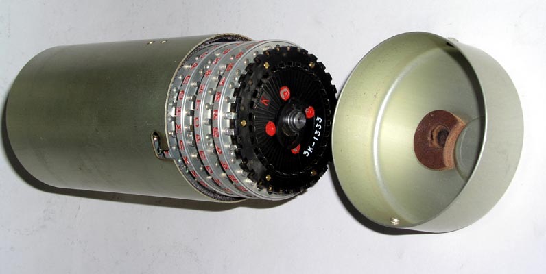
Sets of rotors may be installed in the Fialka or carried in this special
protective metal container inside the cover. A multi-adjustable rotor set is
shown in the container.
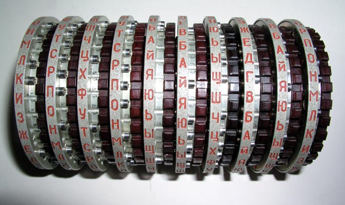
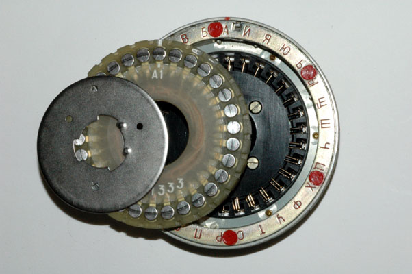
This is a complete set of "3K" series Multi-Adjustable Removable-Wiring-Maze
rotors after removal from the Fialka or from the protective metal container.
The retaining clip that holds the rotors on the shaft is shown on the right
side of this picture.
PLEASE NOTE: The input contact side of all 10 Multi-Adjustable Modular Wiring Maze
rotors after they have been removed from the shaft.
This photograph shows the special retaining clip location that allows 8 of
the rotors to be mounted on the shaft instead of 10. An accessory spacer
fills in the rest of the rotor stack width.
Input Contacts:
The Thirty Input Contacts for Multi-Adjustable Rotor "A".
The output contact sides of all 10 Multi-Adjustable Modular Wiring
Maze rotors after they have been removed from the shaft.
Output Contacts:
The Thirty Output Contacts for Multi-Adjustable Rotor "A".
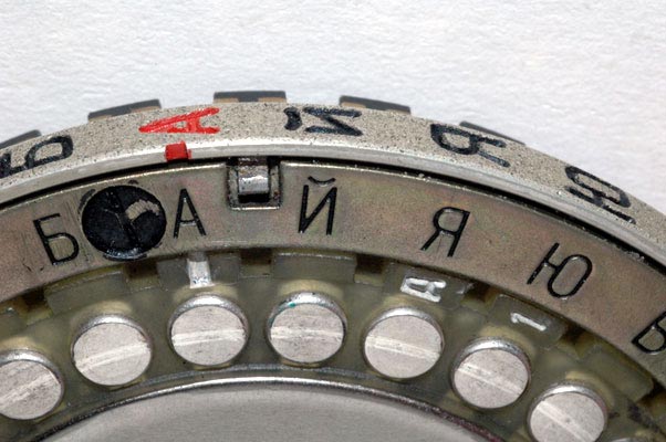
Ring Settings:
In this picture, the Cyrillic letter "A" has been set to the index mark
which, as you will see from the next photograph, is also the outer ring
setting letter "A". When the outer ring is set to this position, it is said
to be in the BASE ring setting position.
This is a closer view of the BASE ring setting in which the outer letter
"A" is set across from the inner letter "A". NOTE:
This is a view of the spring loaded locking pin on a different rotor.
Again, the outer ring has been set to the BASE ring setting in which the outer
letter "A" is set across from the inner letter "A".
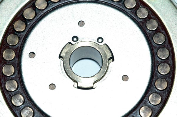
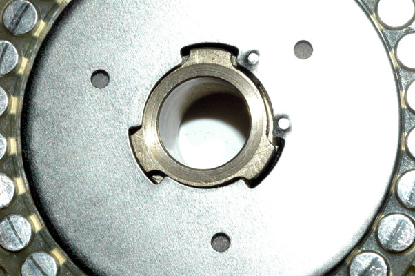
Setting the removable modular wiring mazes:
The removable modular wiring maze is removed by first releasing this metal
disc by rotating it so that it is no longer retained by the tabs on the
central brass cylinder:
In this photograph, the retaining disc has been released from the metal
tabs on the central brass cylinder.
In this photograph, the retaining disc has been moved aside to reveal the
modular wiring maze. Note that the maze has a Cyrillic letter and a number.
The Cyrillic letters on the mazes correspond to the letters of the 10 rotors
BUT, ANY MAZE may be inserted into ANY of the 10 rotors.
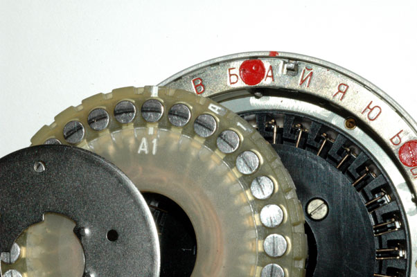
You are looking at side 1 of the modular wiring maze "A". It can be flipped
upside down to reveal side 2. Please also note that the modular wiring maze
has a white line index mark that is pointing to the Cyrillic letter "A". WHEN
THE INDEX MARK ON SIDE 1 OF THE MODULAR WIRING MAZE IS FACING OUTWARDS AND
POINTING TO THE CYRILLIC LETTER "A", THE WIRING MAZE IS IN THE "BASE"
POSITION. When the maze AND the ring setting are in the BASE position, the
rotor is in the OVERALL BASE SETTING and it exactly corresponds to the like-
lettered non-adjustable rotor.
In other words, when multi-adjustable rotor "A" is set to this position, it
has exactly the same wiring and rotor advance blocking pin settings as non-
adjustable rotor "A". These wiring and rotation data are given in tables above
for both the "3K" and "6K" series rotors.
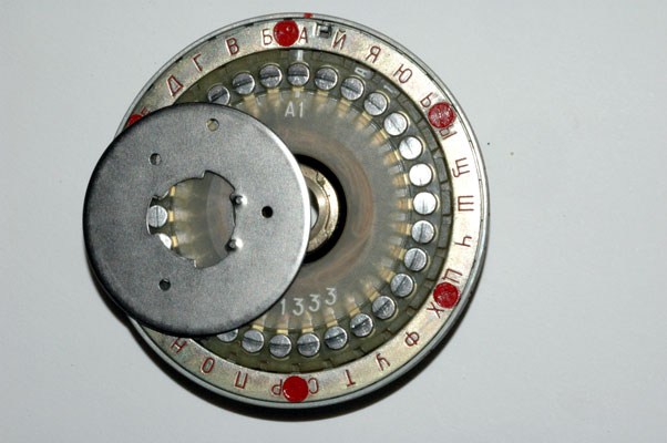
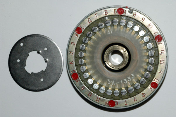
In this photograph, the modular wiring maze has been removed from the
rotor.
This is a close view of the index mark on the modular wiring maze. The
maze is oriented so that side 1 is facing outwards. The large figures "A1"
show that you are looking at side 1 of modular wiring maze "A". The small
figures A 1 printed around the outside of the modular wiring maze are put in
that position to allow the letter and number of the maze to be read even when
the metal disc holding the modular wiring maze is locked in place.
In this photograph, the index mark of the modular wiring maze has been set
to the Cyrillic letter "B" position.
ROTOR MAZE REVERSED AND REINSERTED:
NOTE: This is the setting of adjustable rotor "K" that is shown in a special
column on the right side of the rotor wiring data table. The heading of this
special column is: REVERSED K. This means that multi-adjustable rotor "K" has
had its internal modular "K" wiring maze flipped to the position shown in this
photograph. This special wiring data set in the right column is shown to try
to help clarify what happens to the wired relationship between the 30 input
contacts and 30 output contacts when the removable modular wiring maze is
reversed in the way shown in this photograph. Of course, there are a total of
60 possible orientations of the removable modular wiring maze within the rotor
but it is hoped that showing the data for this one orientation will help
researchers extrapolate all of the other possibilities from this known
wiring.
INSERTING WIRING MAZES INTO DIFFERENT ROTORS: In addition to the 60 possible insertion positions of the modular wiring
maze, remember that these multi-adjustable rotors can also have their outer
Cyrillic letter ring rotated to any of 30 positions. When letter "A" on the
outer ring is adjacent to letter "A" on the rotor, the rotor is set to the
BASE ring setting.
When the Multi-Adjustable rotor is set to the base position with the modular
wiring maze index pointed to the Cyrillic letter "A" and side 1 facing out
AND when the outer letter ring is set so that the Cyrillic letter "A" on the
outer ring is adjacent to the Cyrillic letter "A" on the output face of the
rotor, the rotor is in its OVERALL "BASE" position.
These tables show the Cyrillic and the corresponding numerical
identifier for each of the 30 INPUT contacts in a column on the left side of
the table. The OUTPUT contact that is wired to each of the input contacts is
given by the number in the table under the Cyrillic letter identifying each of
the 10 rotors. To convert this number back into its corresponding Cyrillic
letter, just use the column on the left.
Redundant Note: The table applies to both the Non-Adjustable rotor set and
the Multi-Adjustable rotor set AS LONG AS THE MULTI-ADJUSTABLE ROTORS ARE SET
TO THE BASE POSITION. One final column is presented in the table (for the "3K
series only) to show the internal wiring of multi-adjustable rotor "K" when
the rotor ring setting is first set to the base position and then the modular
wiring maze is flipped upside-down so that side "2" is facing out and the
index mark is adjacent to the Cyrillic Letter "A". With this wiring data it
is possible to determine by extrapolation, the exact internal wiring data for
the multi-adjustable rotors for any of the 60 possible insertion positions of
the modular wiring maze.
Specific Advance Data for all Multi-Adjustable AND Non-Adjustable
Rotors in SERIES "3K" is given in the table above:
Rotor Rotation Advance Blocking Pins:
Although all known Fialka rotors within a 'series' have exactly the same rotor advance blocking
pin placements it is possible, with a considerable amount of effort, to
change the placements. These pins can be removed from the rotors and inserted
into other holes but it is quite difficult to do this. It does not appear
to be a real adjustment of the rotor but rather an assembly convenience and
perhaps a provision for a major engineering revision. To remove the pins, the
6 screws holding the outer ring plate must be unscrewed. Each screw is
covered with red paint that both makes it difficult to unscrew, and also
reveals any attempts to do so. After the outer ring plate is removed, the
pins drop out of their cylindrical holes and can be repositioned. This is so
difficult and complex that for field and operational use, it can safely be
assumed that these pins are always to be found in the positions shown in
the table.
This is a close view of the rotation advance blocking pins for multi-
adjustable rotor "A".
Sample Rotor Rotation Data:
NOTE: I AM ALWAYS INTERESTED IN PHOTOGRAPHING OR BUYING VERY UNUSUAL
ENIGMA-RELATED MATERIALS, PARTS, EARLY COMPUTERS, AND TELEGRAPH KEYS !
Professor Thomas B. Perera
COPYRIGHT NOTICE: (Copyright (c) 2005: Prof. Tom Perera Ph. D.)
The other 10-rotor SET consists of multi-adjustable rotors. Each rotor in this
SET has both an adjustable external ring setting with 30 possible positions
and a modular wiring matrix that can be removed and reinserted in 30 different
orientations. This modular wiring matrix may also be reversed and reinserted
in 30 more orientations. This allows each rotor to have a total of 60 unique
and different internal wiring layouts. The modular wiring matrix may also be
inserted in any of the other 9 rotors in 60 orientations.
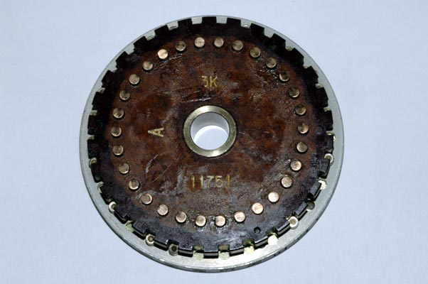
Non-Adjustable Rotor Set:
This is one of the "3K" Series Rotors. You can see the "3K" imprinted on its
input side. These rotors came from Poland and were part of a series that has
totally different wiring from the "6K" Series found in the former
Czechoslovakia.
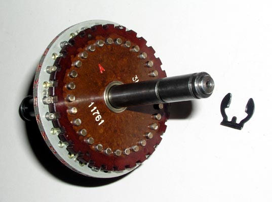

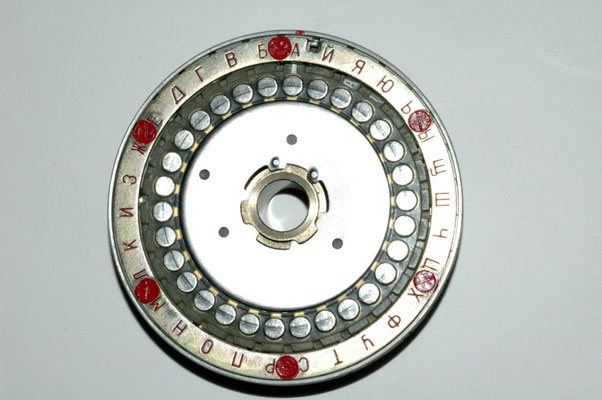
Each rotor has 30 contacts that are identified by 30 letters of the Cyrillic
Alphabet. The letters are stamped around the outer ring of the rotor. The
contacts receive electrical voltages from the input wheel on the right side of
the Fialka and are therefore called the input contacts. These contacts are on
the RIGHT side of the rotors when they are inserted into the Fialka. The
RIGHT side of the rotors face the input wheel which on the far right side of
the Fialka and which carries the voltages from the keyboard to the rotor
stack.
The other side of the rotor contains the 30 output contacts that pass the
electrical voltage out of the rotor and LEFT to the next rotor in the stack or
to the reflector at the far left. Each of these output contacts is identified
by a letter from the Russian Cyrillic Alphabet that is stamped on the outer
ring of the rotor.

 The metal disc has been rotated until it releases the brass central shaft.
Non-Adjustable Rotor Wiring Data:
Click here for Series "6K" wiring data from Paul
Reuvers.
Ezequiel Guerrero Romero B. Sc. has created tables of the
wiring of all Multi-Adjustable Fialka Rotors in the 3K and 6K -series with
their wiring maze reversed that you can view by clicking here.
Non-Adjustable Rotor Advance Data:
(Click here for the Series "6K" Rotor
Advance Data.)
(Click here for the Series "6K" Non-Adjustable
AND Multi-Adjustable Rotor Advance Data.)
ROTOR ADVANCE BLOCKING PIN LOCATIONS FOR NON-ADJUSTABLE AND
MULTI-ADJUSTABLE MODULAR-WIRING-MAZE ROTORS
FOR RUSSIAN M-125-MN AND M-125-3MN FIALKA CIPHER MACHINES
(Click here for the Series "6K" Non-Adjustable
AND Multi-Adjustable Rotor Advance Data.)
These pins determine whether the rotor will advance or not as each letter is
typed in. These pins block the advance of rotors by blocking specific advance
cogs underneath the rotor stack.
NOTES ON THE ROTATION OF THE ROTORS:
Sample rotation data for all 10 rotors for the first 20 letters typed into the
Fialka are shown in a table below:
SAMPLE ROTOR ADVANCING DATA FOR NON-ADJUSTABLE AND
MULTI-ADJUSTABLE MODULAR-WIRING-MAZE ROTORS
FOR RUSSIAN M-125-MN AND M-125-3MN FIALKA CIPHER MACHINES
NOTES ON THE ROTATION OF THE ROTORS:
EXAMPLE OF THE USE OF THIS TABLE:
Multi-Adjustable Removable-Wiring-Maze Rotor Set:
This is a "3K" series rotor as indicated by the "3K" inscribed on the
input side. These "3K" series rotors are known to have come from Poland.
Another series that has a "6K" inscribed on its input side is known to have
come from the former Czechoslovakia. This suggests the possibility that these
two rotor series were used in different countries or by different military
organizations.
Each rotor has 30 contacts that are identified by 30 letters of the Cyrillic
Alphabet. They receive electrical voltages from the input wheel on the right
side of the Fialka and are called the input contacts. These contacts are on
the RIGHT side of the rotors when they are inserted into the Fialka. The
RIGHT side of the rotors face the input wheel which on the far right side of
the Fialka and which carries the voltages from the keyboard to the rotor
stack.
The other side of the rotors have the 30 output contacts that pass the
electrical voltage out of the rotor and LEFT to the next rotor in the stack or
to the reflector at the far left. Each of these output contacts is identified
by a letter from the Russian Cyrillic Alphabet. If you look closely at the
output contacts you may be able to see the "A 1" that identifies side 1 of the
removable modular wiring maze for rotor "A".
Adjusting the Multi-Adjustable Rotors:
The Ten multi-adjustable rotors can have their RING SETTINGS set to any one of
30 possible locations. They can also have their REMOVABLE MODULAR WIRING
MAZES set to any one of 60 possible locations. These settings are explained
below:
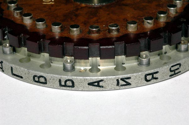
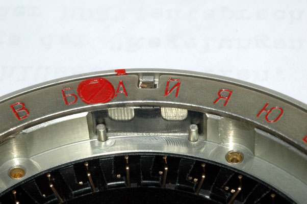
The outer ring has 30 Cyrillic letters and any one of these letters may be set
across from the index mark by pushing a spring-loaded locking pin inwards as
shown below:
The outer ring is rotated after pressing inwards on the small tab that is
visible in this picture. This pin CAN ONLY BE PRESSED INWARDS AFTER THE
REMOVABLE WIRING MAZE HAS BEEN REMOVED.
The 30 wired connections between the 30 input contacts and the 30 output
contacts are made by a modular removable wiring maze. The modular wiring maze
is removed from the rotor by following the steps shown in the next
photographs: First, the retaining disc is rotated until it is released from
the tabs on the brass central shaft:
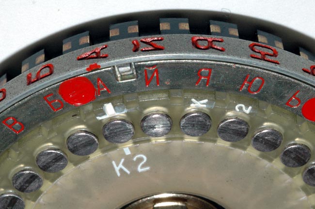
In the following photograph, the modular wiring maze has been removed from
rotor "K" and flipped upside down so that side 2 is facing outwards. The
index mark on the modular wiring maze is pointing to the Cyrillic letter
"A".
 This photograph shows rotor "K" with its removable modular wiring maze FLIPPED
OVER OR REVERSED so that side "2" of the maze is facing outward and its index
mark is pointing to the letter "A" position. THIS IS THE SETTING OF ROTOR "K"
THAT IS REFERRED TO AS "REVERSED K" IN THE 'SPECIAL' COLUMN ON THE RIGHT SIDE
OF THE ROTOR WIRING TABLE. The wiring data shown in the special right column
of the table show the connections between the input contacts and the output
contacts when the modular wiring maze is reversed in rotor "K" so that it is
in this position.
This photograph shows rotor "K" with its removable modular wiring maze FLIPPED
OVER OR REVERSED so that side "2" of the maze is facing outward and its index
mark is pointing to the letter "A" position. THIS IS THE SETTING OF ROTOR "K"
THAT IS REFERRED TO AS "REVERSED K" IN THE 'SPECIAL' COLUMN ON THE RIGHT SIDE
OF THE ROTOR WIRING TABLE. The wiring data shown in the special right column
of the table show the connections between the input contacts and the output
contacts when the modular wiring maze is reversed in rotor "K" so that it is
in this position.
It is important to remember that the wiring mazes from one rotor can be
removed and reinserted into any other rotor in 60 different orientations.
Please notice that the modular wiring maze has both an index mark and a
Cyrillic letter and a number 1 or 2. The modular wiring maze can be inserted
into a rotor with the index mark pointing to any of the 30 Cyrillic letter-
identified locations around the rotor. The modular wiring maze can be
inserted into the rotor with either side 1 or side 2 facing up. The "BASE"
positioning of a modular wiring maze is when the index mark points to the
Cyrillic letter "A" and side 1 is facing outward.
Multi-Adjustable Rotors Wiring Data:
The exact wiring between the 30 input and 30 output connections for the 10
multi-adjustable rotors set to the OVERALL BASE position is identical to the
wiring of the non-adjustable rotors and the data for the "3K" series is shown
in the previous wiring data table.
(Click here for the wiring data for the "3K" series
rotors.)
(Click here for the wiring data for the "6K" series rotors
from Paul Reuvers.)
Ezequiel Guerrero Romero B. Sc. has created tables of the
wiring of all Multi-Adjustable Fialka Rotors in the 3K and 6K -series with
their wiring maze reversed that you can view by clicking here.
Multi-Adjustable Rotors Advance Blocking Pin Data:
(Click here for the Series "6K" Multi-Adjustable
AND Non-Adjustable Rotor Advance Data.)
The actual rotation of the rotors is controlled by the placement of the metal
pins adjacent to each of the contacts. These pins block or lock-out the drive
mechanism and determine which rotors will not rotate. This photograph shows
several of the pins and several of the un-pinned locations. A detailed table
of the locations of all of the pins in all of the rotors in series "3K" and
series "6K" may be found above.
Sample rotation data for all 10 rotors of series "3K", for the first 20
letters typed into the Fialka are shown in the table above. Within a 'series'
they are identical for non-adjustable rotors AND multi-adjustable rotors set
to the base position.
The other sections in the FIALKA MENU above describe and display the general
introduction, the Model M-125-MN, the much more complex model M-125-3MN, the
rotors, power supply and cables and the cover and accessories.
Montclair State University
Internet On-Line ENIGMA museum: (Requires connection to internet)
http://w1tp.com/enigma
I ask you to type my email address as
follows with no spaces between words:)
Internet On-Line Telegraph & Scientific Instrument Museum:
http://w1tp.com
or:
http://www.chss.montclair.edu/~pererat/telegrap.htm:
Although all the pictures and text are copyrighted, you may use any of them
for your own personal applications including public lectures and
demonstrations, publications and websites as long as you mention the
www.w1tp.com/enigma Museum. If you plan to offer them for sale to the public
in any form, you must email me for permission which I will generally grant as
long as you mention my museum: http://w1tp.com/enigma. My email address is
given at the bottom of this page. Some of the material may require contacting
other copyright owners for commercial use and I will inform you by email.
Please also see the disclaimer of warranty.