Descriptions, Photographs, and Partial Disassembly of the
M-125-3MN / -3MP3 Fialka:
The following section describes and displays the Model M-125-3MN/-3MP3
Fialka. This model is much more complex than the M-125-MN model. The
differences are described below:
The M-125-3MN/-3MP3 has many complex features that are not included
in the M-125-MN. These include:
1. A multilingual keyboard.
2. A mechanical switch along the right side of the keyboard
that modifies keyboard function.
3. A 3-position lever on the back of the Fialka that modifies paper tape
punch operation.
4. A large matrix switch that alters the wiring of the programming matrix and
therefore the effect of the programming cards.
5. A rotary switch located under the base of the Fialka.
6. A position on the input rotor switch that stops rotation of the rotors and
character counting as characters are typed in.
7. An extended copyholder.
All of these features will be shown and described in the following page:
Descriptions, Photographs, and Partial Disassembly of the
M-125-3MN/-3MP3 Fialka:
Note: These pictures show a model M-125-3MP2 Fialka which is very similar to a
model M-125-3MN, and the model M-125-3MP3. The only differences appear to be
slight variations in the keyboards.
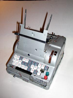
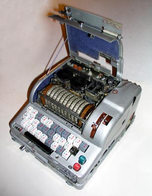
External Appearance and Features:
The left side view of the M-125-3MN Fialka shows the copy holder with its
extensions, the character counter and the slot for the paper programming card.
The carrier for the paper programming card being pulled out of the left side
of the Fialka to allow insertion of the card.
Closer view of the carrier for the paper programming card opening to allow
insertion of the card.
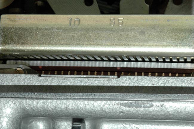
Closer view of the contacts that are activated by the programming card.
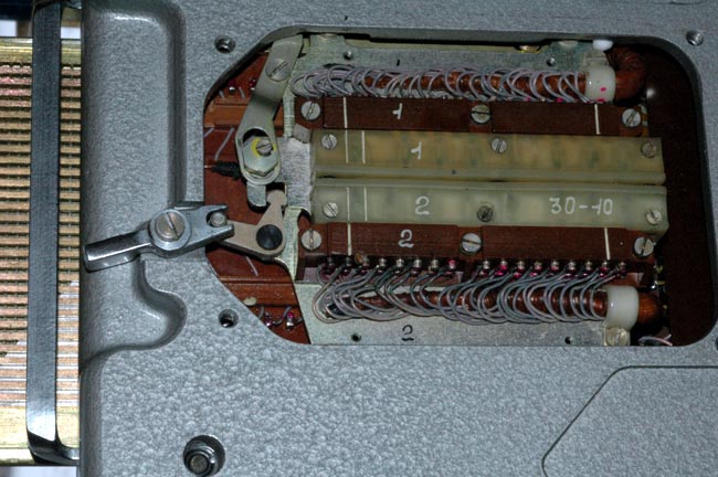
The underside of the M-125-3MN showing the unique chromed programming card
matrix switch lever that changes all of the contacts in the card reader. This
switch is not found in the M-125-MN model.
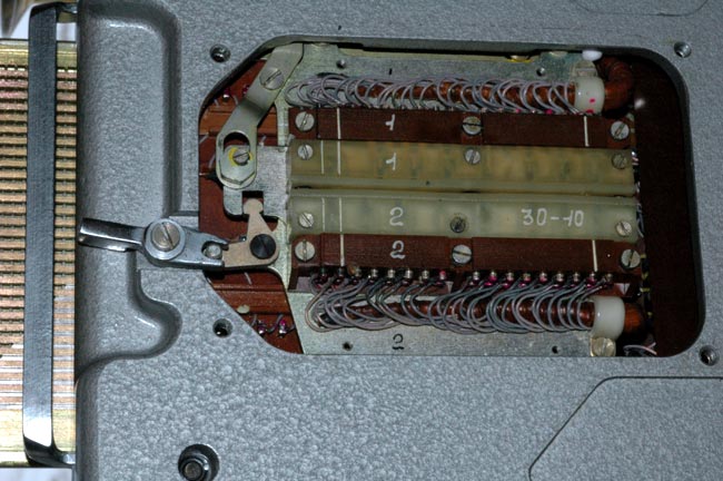
Removing the cover over the switch reveals the complicated mechanism. The
lever moves the white plastic central contacts to the right when it is
activated as shown in the next photograph. This switch is not found in the M-
125-MN model.
In this photo the lever has moved the white plastic central contacts to the
right thus changing the entire wiring of the programming card reader matrix.
This switch is not found in the M-125-MN model.
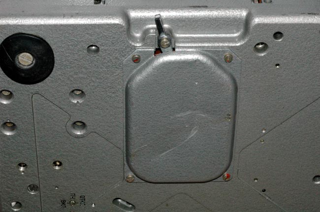
Another unique feature of the M-125-3MN model is this rotary switch that is
located near the center of the bottom of the base of the Fialka. This switch
is not found in the M-125-MN model.
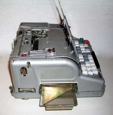
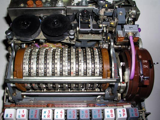
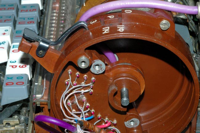
The Right side of the Fialka showing the copy holder and input wheel
levers. The switch under the rotors, and the hole for the hand crank
that allows manual operation of the Fialka rotors are just barely visible.
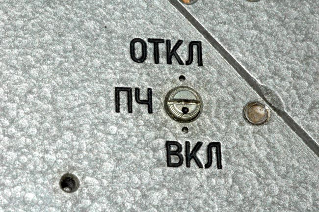
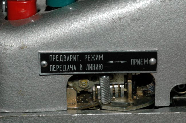
The switch (left) and paper tape control lever (right) are part of the
switch assembly that is located on the right side of the Fialka adjacent to
the input wheel. In this M-125-3MN model, the switch in the 0 position as
shown disables rotation of the rotors and incrementing of the character
counter. In the M-125-MN model, this position of the switch has no effect.

The Rear of the Fialka showing the three position lever that is not found
on the M-125.MN model. It is located half way between the center and the left
corner. The lever must be pushed downwards to unlock it and allow it to be
set to one of the three positions.
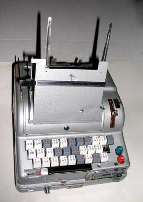
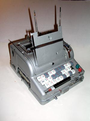
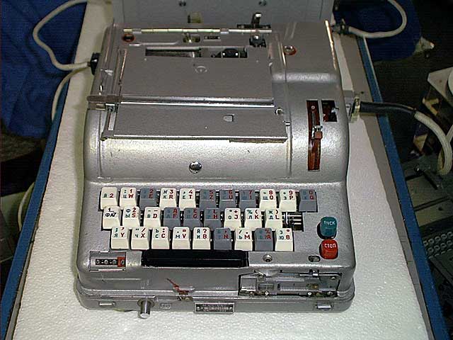
A front view of the Fialka showing the keyboard with the paper tape reader
on the right and the character counter on the left.
This mechanical switch located under the right side of the keyboard
modifies the function of the keyboard. This switch is not found on the
Model M-125-MN Fialka.
This picture shows the mechanical switch under the right side of the
keyboard with the cover removed. The knurled and slotted activating pin is
positioned between the left and right positions. It modifies the function of
the keyboard. This switch is not found on the Model M-125-MN Fialka.
The Fialka connected to its 24 volt DC power supply.
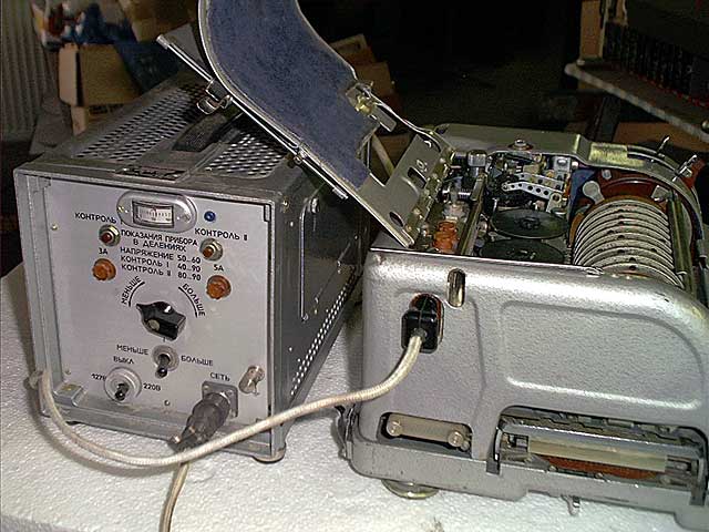
The left side of the Fialka connected to its 24 volt DC power supply.
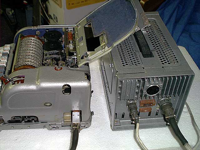
The right side of the Fialka connected to its 24 volt DC power supply.
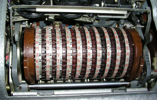
The 10 rotors after the cover door is opened. The index bar is lowered in
place in front of the rotors to allow accurate setting.
Another view of the 10 rotors after the cover door is opened. The index
bar is lowered in place in front of the rotors to allow accurate setting.
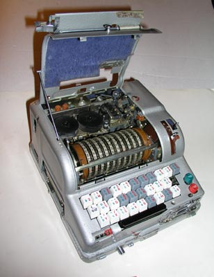
Appearance and Features of the Fialka seen with cover removed:
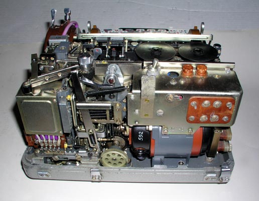
A top view of the Fialka with cover removed (3 screws). The power switch
and fuses are in the left rear. The paper tape printer ribbon reels, the
printer and the paper tape punch are behind the 10 rotors. The brown reflector
is on the left end of the rotor stack. The brown input wheel is on the
right end of the rotor stack. The keyboard and paper tape reader with its
manual paper tape feed wheel are in front.
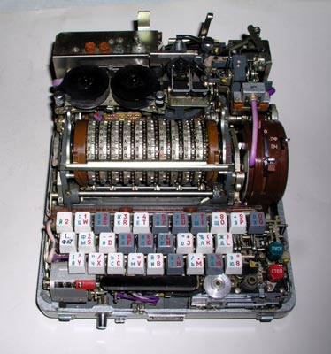
A closer view of the power switch, fuses, the paper tape printer ribbon
spools, the printer, and the punch mechanism. The unique 3 position lever is
seen extending upwards from the rear of the mechanism.
A view of the back of the Fialka after removal of the cover. Note the
3-position lever to the left of the center of the machine. It appears to
modify the functioning of the paper tape punch mechanism. This lever is not
found on the model M-125-MN Fialka.
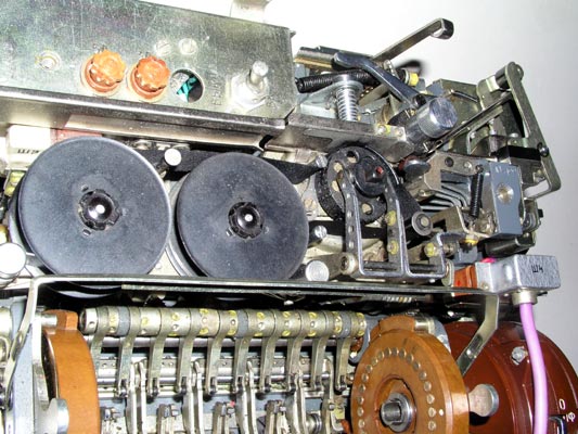
Note the metal box on the left corner of the mechanism. It houses the
paper tape punch solenoids as shown in the next photograph.
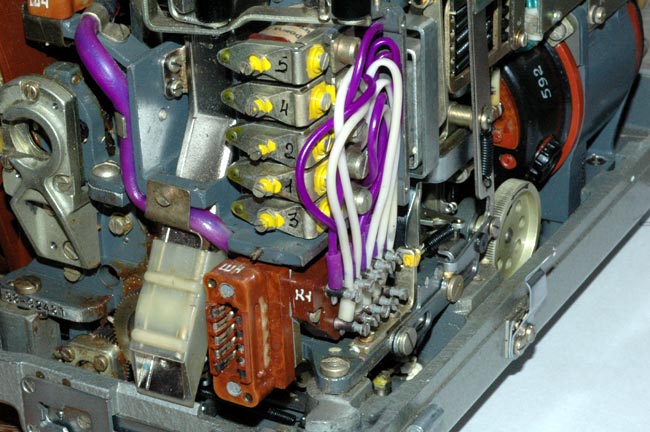
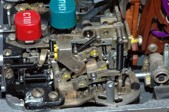
The 5 paper tape punch operating solenoids are located under a metal cover
in the back right corner of the Fialka. Note also the 3-position switch lever
with the three detent positions located in back of and below the colored
wires. It is located in front of the manual mechanism drive wheel with its
arrow indicating the correct direction of rotation.
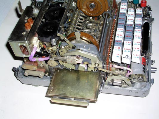
The left side view of the Fialka with the cover removed showing the programming
card holder under the rotors and the reflector.
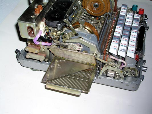
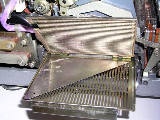
Another left side view of the Fialka with the cover removed showing the
programming card holder pulled all the way out and opened to accept a
programming card.
A close view of the programming card holder pulled all the way out and
opened to accept a programming card.
Front view of the Fialka showing the 10 rotors with the index bar in place
to facilitate setting the rotor positions accurately.
A closer view of the 10 rotors with the index bar raised to permit removal
of the rotor stack.
The two rounded levers that push the reflector on the left and the input wheel
on the right inward have been pulled forward so that the reflector and input
wheel may be pushed outwards to allow the rotor stack to be removed.
These are the Non-Adjustable rotors. They are described in much more detail
in the special detailed section on rotors and rotor
movement.
The Non-Adjustable Rotor Set:
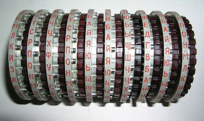
The 10 rotor stack of Non-adjustable rotors is shown here after
removal from the Fialka.
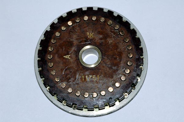
The input contact side of one of the 10 non-adjustable rotors after
removal from the rotor shaft. Note the grease which lubricates the rotor and
improves contact reliability.
NOTE:
This is a rotor from the "3K" series. These rotors were found in Poland.
Their wiring is very different from the "6K" Series of rotors that were found
in the former Czechoslovakia. These different series are described in much
more detail in the Rotor description pages.
The output contact side of one of the 10 non-adjustable rotors after
removal from the rotor shaft.
The internal hand-wired set of connections between the input contacts and
the output contacts is called a wiring maze. It can be inspected or repaired
by removing a metal disc as shown here. The wiring of these non-adjustable
rotors is not designed to be changed.
NOTE: Please refer to the section on rotors
for a more complete set of photographs and descriptions of the non-
adjustable and multi-adjustable rotors and their wiring and rotation data.
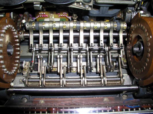
The drive mechanisms that produce the rotation of alternate rotors.
The lower horizontal bar activates cogs that pull forward on the bottoms of
rotors 2, 4, 6, 8 and 10 (counting from left to right) and rotate them so that
the tops of the rotors move AWAY from the keyboard.
The upper horizontal bar activates cogs that pull back on the bottoms of
rotors 1, 3, 5, 7 and 9 (counting from left to right) and rotate them so that
the tops of the rotors move TOWARD the keyboard.
A set of 10 spring-loaded arms with rollers holds the 10 rotors in their
detent positions.
Highly detailed photographs and explanations of the rotation of the rotors are
given in this special rotor page.
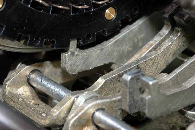
A very close view of one of the cogs that move toward the back of the
Fialka causing the rotor to rotate its top TOWARD the keyboard.
The cog mechanism and the advance blocking feeler for the second rotor to the
right of this one are also visible in the foreground. Much
more detailed descriptions, photographs, and tables explain the rotation of
the rotors in this link:
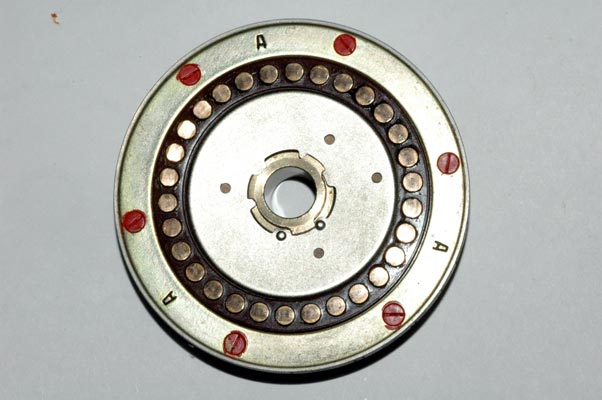
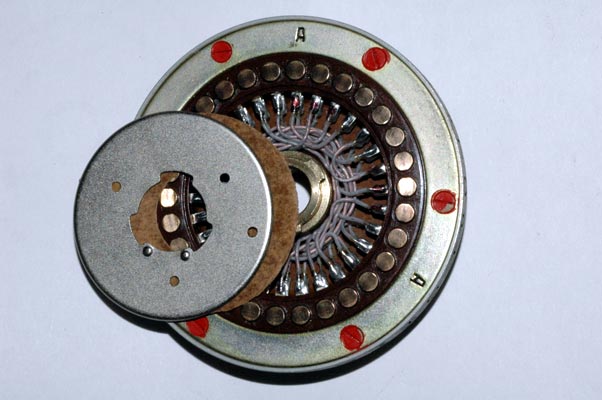
The reflector located on the left end of the rotor stack. Notice the three
bundles of wires coming down out of the reflector. (The less complex Model M-
125-MN has only one bundle of wires exiting the reflector). It is thought
that these 3 bundles of wires may be part of a circuit that allows the Fialka
to represent more Cyrillic letters than just the 30 represented by the 30
rotor contacts and keyboard keys.
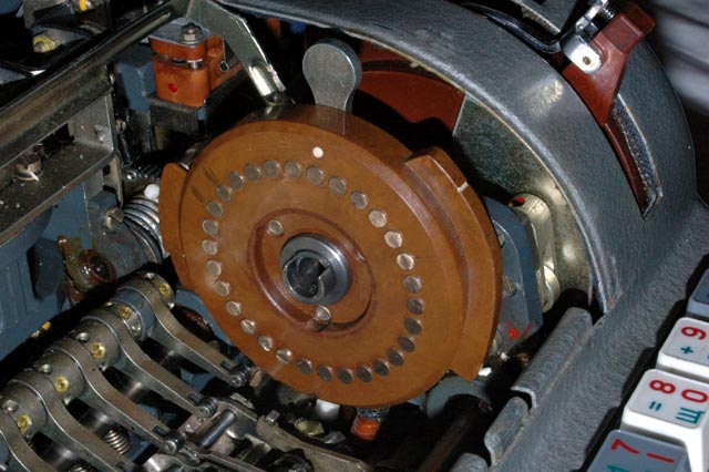
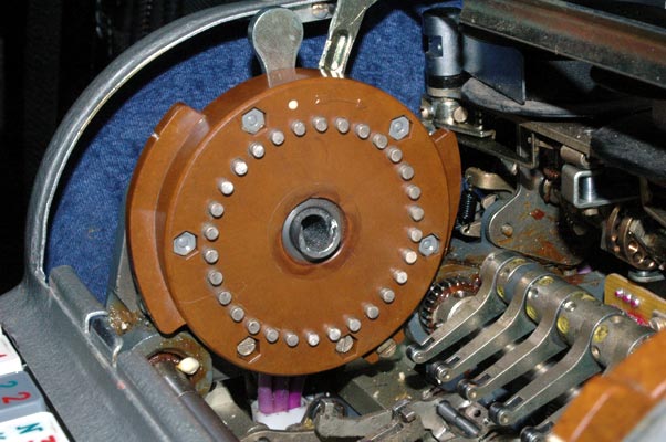
The input wheel located on the right end of the rotor stack. If you look
closely, you can see a bundle of wires coming up into the input wheel.
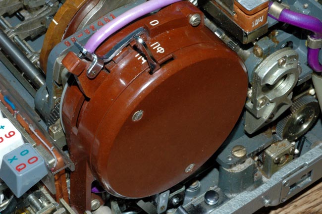
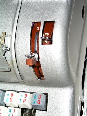
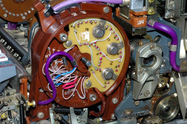
A closer view of the switch assembly adjacent to the input wheel shows the
3 position switch lever on the left and the paper tape control lever on the
right. Notice that the 3-position switch is in the uppermost position. In
this position, it disables rotation of the rotors and incrementing of the
character counter. It does not seem to have any function in the top position
in the M-125-MN Fialka.
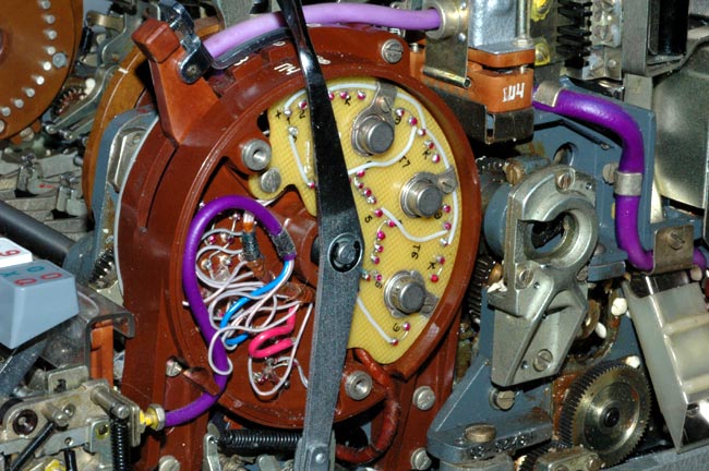
Removing the cover of switch assembly that is adjacent to the input wheel
shows the internal circuitry and paper tape punch control lever mechanism.
Removing the paper tape punch control lever from the switch
assembly shows the internal circuitry more clearly.
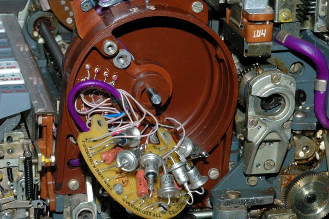
Pulling the circuit board outwards reveals the 7 power diodes and
other components.
Pulling the circuit board farther out of the way reveals the switching
mechanism that is activated by the lower two positions of the 3 position
switch adjacent to the input wheel.
The uppermost position ( "O" ) of the switch lever completely disables rotor
rotation and character counter activation in the M-125-3MN Fialka. It has no
effect at all on the functioning of the M-125-MN Fialka.
NOTE: I AM ALWAYS INTERESTED IN PHOTOGRAPHING OR BUYING VERY UNUSUAL ENIGMA-RELATED MATERIALS, PARTS, EARLY COMPUTERS, AND TELEGRAPH KEYS !
Professor Thomas B. Perera
Montclair State University
COPYRIGHT NOTICE: (Copyright (c) 2005: Prof. Tom Perera Ph. D.)
Although all the pictures and text are copyrighted, you may use any of them
for your own personal applications including public lectures and
demonstrations, publications and websites as long as you mention the
www.w1tp.com/enigma Museum. If you plan to offer them for sale to the public
in any form, you must email me for permission which I will generally grant as
long as you mention my museum: http://w1tp.com/enigma. My email address is
given at the bottom of this page. Some of the material may require contacting
other copyright owners for commercial use and I will inform you by email.
Please also see the disclaimer of warranty.