Descriptions, Photographs, and Partial Disassembly of the
M-125-MN Fialka:
The following section describes and displays the Model M-125-MN Fialka. It is much less complex than the multilingual M-125-3MN/-3MP3 model which is shown in other pages accessed by the menu above.
Differences between the Model M-125-MN and the Model M-125-3MN / -3MP3
Fialkas:
The M-125-MN does not include a number of complex features that are found
in the M-125-3MN/-3MP3.
These include:
1. A multilingual keyboard.
2. A mechanical switch along the right side of the keyboard
that modifies keyboard function.
3. A 3-position lever on the back of the Fialka that modifies paper tape
punch operation.
4. A large matrix switch that alters the wiring of the programming matrix and
therefore the effect of the programming cards.
5. A rotary switch located under the base of the Fialka.
6. A position on the input rotor switch that stops rotation of the rotors and
character counting as characters are typed in.
7. An extended copyholder.
All of these additional features of the M-125-3MN/-3MP3 Fialka are shown
in pages in the Fialka Menu above:
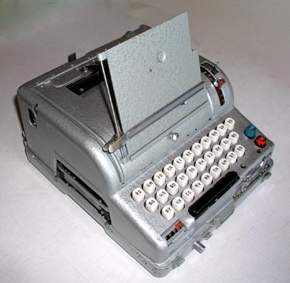
External Appearance and Features:
Left side view of the model M-125-MN Fialka showing the copy holder, the
letter counter and the slot for inserting the paper programming card.
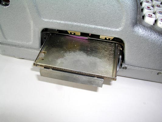
Closer view of the carrier for the paper programming card being pulled out.
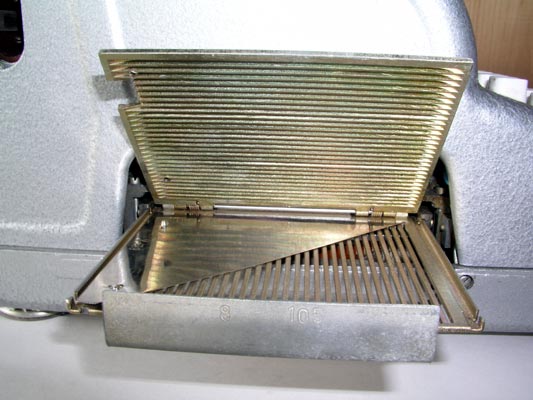
Closer view of the carrier for the paper programming card fully open to
allow insertion of the card.
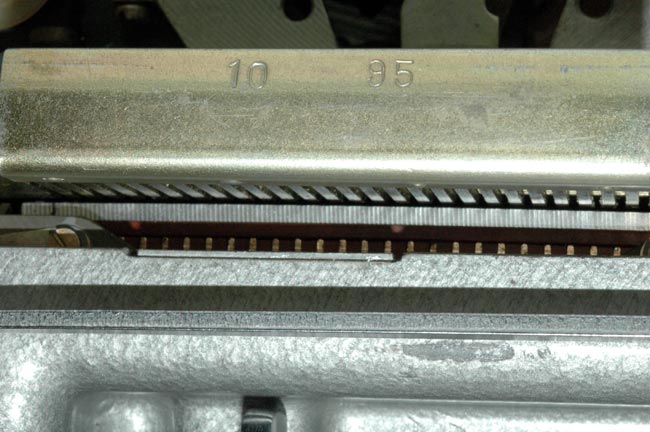
Much closer view of the carrier for the paper programming card showing
the contacts that read the holes in the cards.
The Right side of the Fialka showing the copy holder, the switches to the
right of the input wheel, the switch under the rotors, and the hole for the
hand crank that allows manual operation of the Fialka.
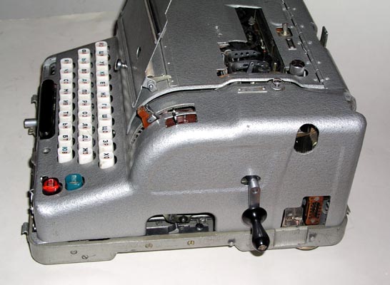
The Right side of the Fialka showing the switch located under the rotors
and the hand crank that allows manual operation of the Fialka rotors.
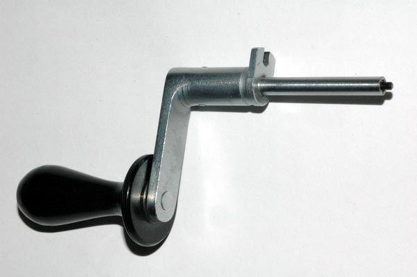
The hand crank that allows manual operation of the Fialka rotors.
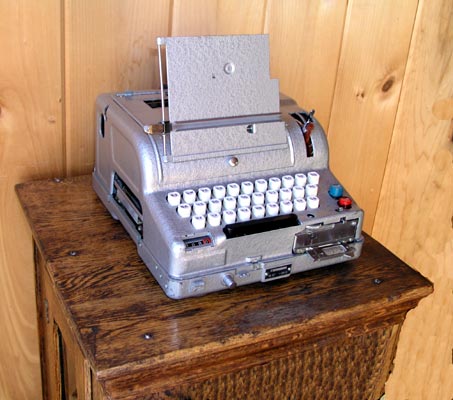
The Fialka resting on a wooden pedestal.
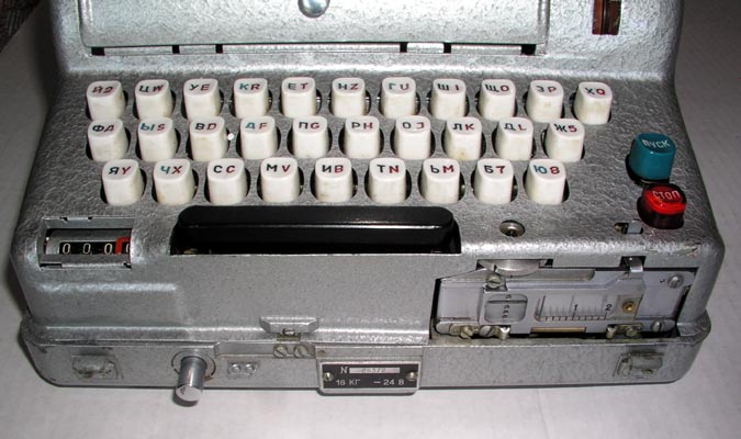
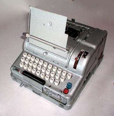
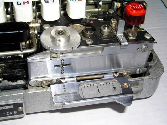
A closer view of the keyboard, the paper tape reader, and the character
counter. The reset button for the counter is located under the counter
between the counter and the space bar.
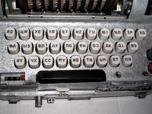
A Much closer view of the Russian keyboard.
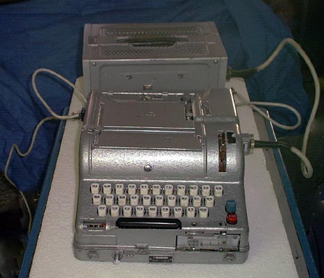
The Fialka connected to its 24 volt DC power supply.
The left side of the Fialka connected to its 24 volt DC power supply.

The right side of the Fialka connected to its 24 volt DC power supply.
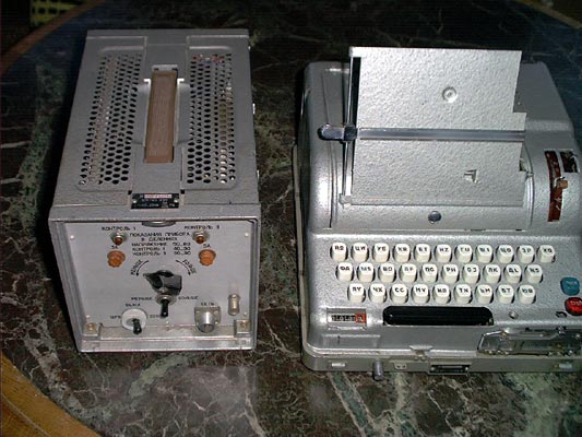
The Fialka and its 24 volt DC power supply.
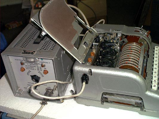
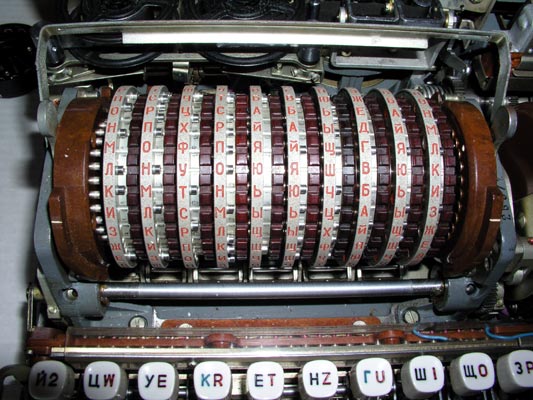
The 10 rotors after the cover door is opened. The index bar is raised
to the open position to allow the removal of the rotors.
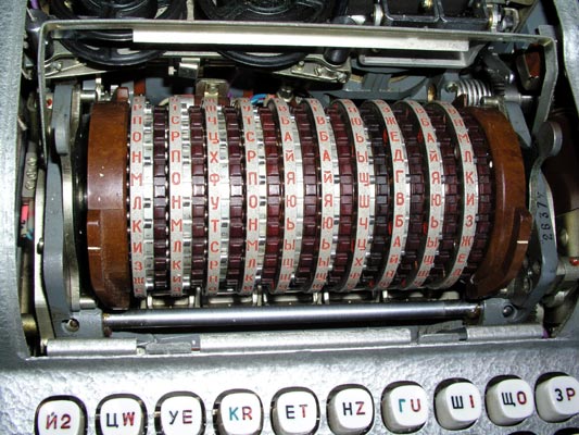
A closer view of the 10 rotors after the cover door is opened. The
index bar is raised to allow removal of the rotors.
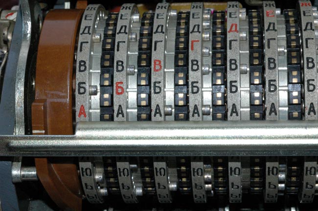
A close view of the 10 rotors with the index bar lowered and clicked into
position to aid in the accurate setting of the rotor positions. All rotors
have been set to the "A" position.
Appearance and Features of the Fialka seen with cover removed:
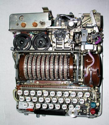
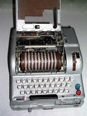
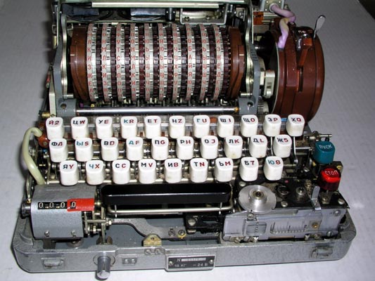
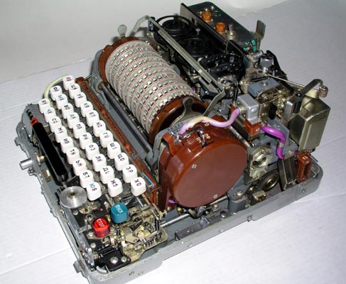
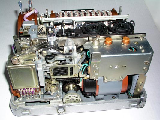
A top view of the Fialka with cover removed (3 screws). The power switch
and fuses are seen in the left rear. The paper tape printer ribbon reels,
printer, and paper tape punch are behind the 10 rotors. The brown reflector
is on the left end of the rotor stack. The input wheel is on the
right end of the rotor stack. The keyboard and manual paper tape feed wheel
are in front.
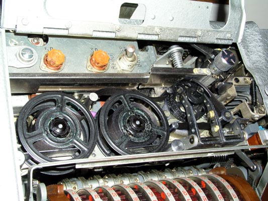
A closer view of the power switch, fuses, the paper tape printer ribbon
spools, the printer, and the punch mechanism.
A closer view of the paper tape reader mounted on the front of the Fialka.
A left side view of the Fialka with the cover removed showing the
programming card slot under the rotors and the reflector.
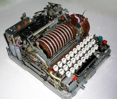
A front view of the Fialka showing the 10 rotors, the keyboard, the
counter, and the paper tape reader with the round paper tape advance wheel.
A closer view of the 10 rotors with the index bar raised to permit removal
of the rotor stack. The rounded metal handles on the two levers that push the
reflector on the left and the input wheel on the right inward have been moved
forward and the reflector and input wheel have been pushed outwards to allow
the rotor stack to be removed. These are the non-adjustable rotors. They
will be described in more detail later.
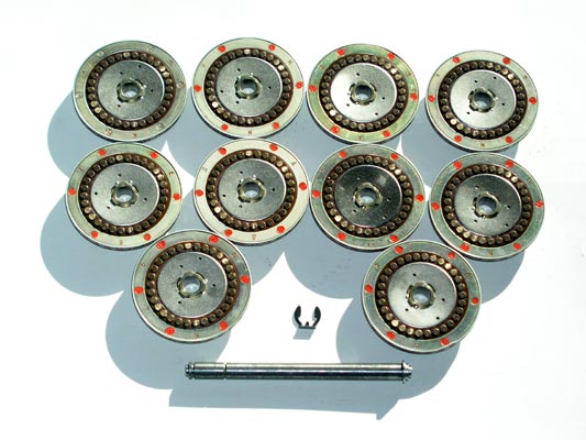
The Non-Adjustable Rotor Set shown below was found in the model
M-125-MN Fialka:
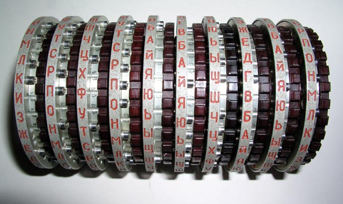
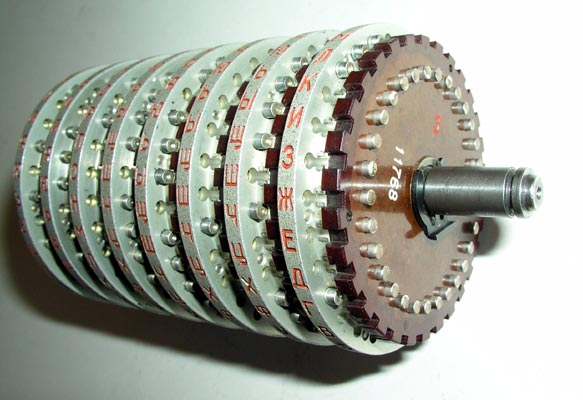
The 10 rotor stack of non-adjustable rotors is shown here after
removal from the Fialka.
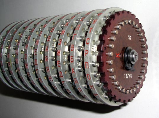
The 10 rotor stack of non-adjustable rotors showing the 30 spring loaded
input contacts and the retaining clip that keeps the rotors on the shaft.
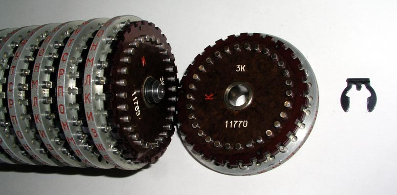
The 10 rotor stack with the retaining clip removed and rotor "K" slid
off the shaft.
NOTE:
As you can see from the "3K" inscribed on the input side of this rotor, it is
one of the "3K" Series Rotors. These rotors came from Poland and were
part of a series that has totally different wiring from the "6K" Series found
in the former Czechoslovakia. These series are described in more detail in the
rotor section of these pages.
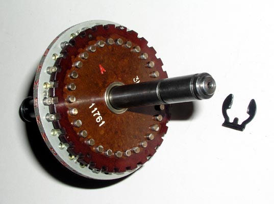
The 10 rotor stack with all but rotor "A" removed from the shaft.
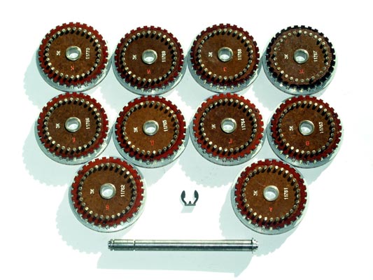
The input contact (right) sides of all 10 non-adjustable rotors after
removal from the shaft.

The output contact (left) side of a non-adjustable rotor on the shaft.
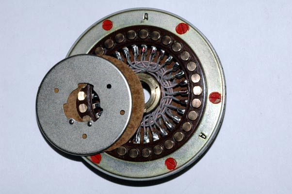
The internal hand-wired set of connections between the input contacts and
the output contacts is called a wiring maze. It can be inspected or repaired
by removing a metal disc as shown here. The wiring maze of one of these
non-adjustable rotors is not designed to be changed.
The output contact sides of all 10 non-adjustable rotors after removal from
the shaft.
The shaft with the retaining clip in place to allow 8 rotors to be used
instead of 10. A special filler with contacts on both sides is used to fill
in the remaining space.
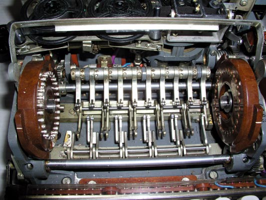
The drive mechanisms that produce the rotation of alternate rotors.
The lower horizontal bar activates cogs that pull forward on the bottoms of
rotors 2, 4, 6, 8 and 10 (counting from left to right) and rotate them so that
the tops of the rotors move AWAY from the keyboard.
The upper horizontal bar activates cogs that pull back on the bottoms of
rotors 1, 3, 5, 7 and 9 (counting from left to right) and rotate them so that
the tops of the rotors move TOWARD the keyboard.
A set of spring-loaded roller-equipped arms lock all 10 rotors into their
detent positions.
Highly detailed photographs and explanations of the rotation of the rotors are
given in this special rotor page
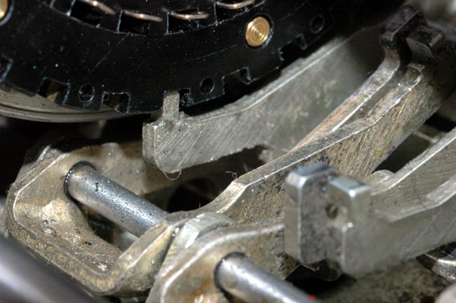
A very close view of one of the cogs that move toward the back of the
Fialka causing the rotor to rotate its top TOWARD the keyboard.
The cog mechanism and the advance blocking feeler for the second rotor to the
right of this one are also visible in the foreground. A much more detailed description, photographs, and tables explain the
rotation of the rotors in this link:
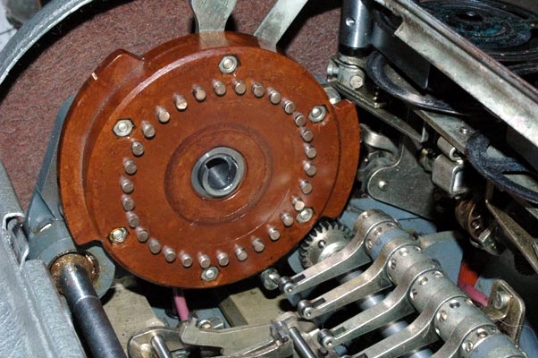
The reflector located on the left end of the rotor stack. Notice the one
bundle of wires coming down out of the reflector. It is thought that this
bundle of wires may be part of a circuit that allows the Fialka to represent
more Cyrillic letters than just the 30 activated by the 30 rotor contacts.
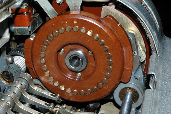
The input wheel located on the right end of the rotor stack. The input
wheel has a bundle of wires coming up into it as seen in this photograph.
The right side of the Fialka showing the input wheel and adjacent lever
and switch described in detail in the following photograph captions.
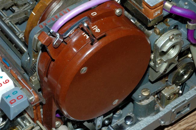
A closer view of the input wheel and adjacent switch assembly shows the 3
position switch lever on the left and the paper tape punch control lever on
the right.
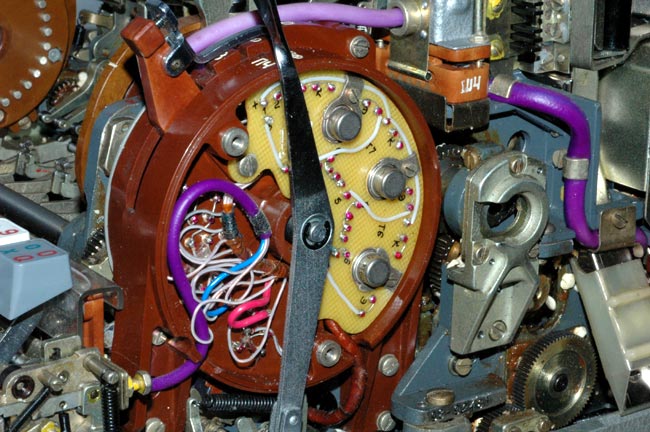
Removing the cover of the switch assembly that is adjacent to the input
wheel reveals the internal circuitry and paper tape punch control lever
mechanism.
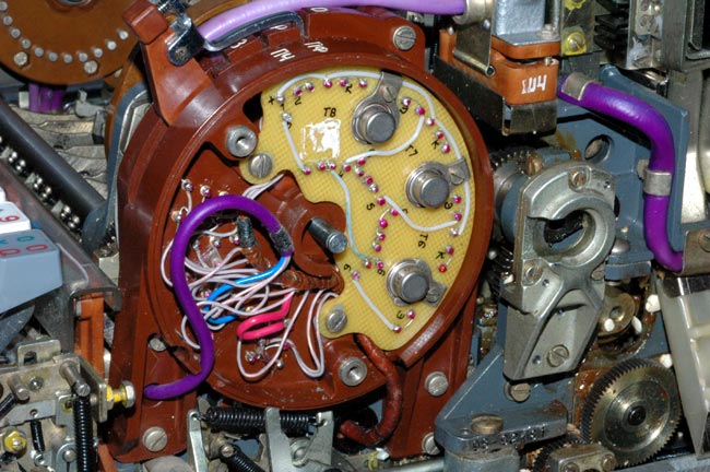
Removing the paper tape punch control lever from the switch assembly
adjacent to the input wheel shows the internal circuitry more clearly.
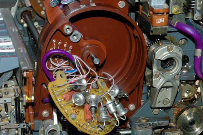
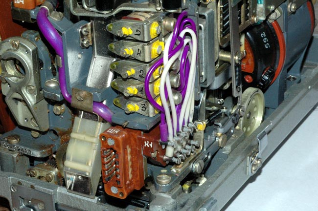
Pulling the circuit board outwards reveals the 7 power diodes and
other components.
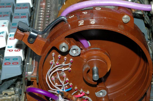
Pulling the circuit board farther out of the way reveals the switching
mechanism that is activated by the lower two positions of the 3 position
input wheel switch. The uppermost position of the switch lever does nothing
in the M-125-MN Fialka but completely disables rotor rotation and character
counter activation in the M-125-3MN / -3MP3 Fialka.
The back of the Fialka with the cover removed showing the drive motor. The
metal box at the left contains the 5 paper tape punch operating solenoids
shown in the next photograph.
The 5 paper tape punch operating solenoids are located under a metal cover
in the back right corner of the Fialka.
Detailed Rotor Wiring and Rotation Data, Photographs, and
Descriptions may be viewed at this link:
NOTE: I AM ALWAYS INTERESTED IN PHOTOGRAPHING OR BUYING VERY UNUSUAL ENIGMA-RELATED MATERIALS, PARTS, EARLY COMPUTERS, AND TELEGRAPH KEYS !
Professor Thomas B. Perera
Montclair State University
COPYRIGHT NOTICE: (Copyright (c) 2005: Prof. Tom Perera Ph. D.)
Although all the pictures and text are copyrighted, you may use any of them
for your own personal applications including public lectures and
demonstrations, publications and websites as long as you mention the
www.w1tp.com/enigma Museum. If you plan to offer them for sale to the public
in any form, you must email me for permission which I will generally grant as
long as you mention my museum: http://w1tp.com/enigma. My email address is
given at the bottom of this page. Some of the material may require contacting
other copyright owners for commercial use and I will inform you by email.
Please also see the disclaimer of warranty.