Fialka Cover, Accessories, and Multi-Adjustable Modular Wiring Matrix
rotor set:
Descriptions, and Photographs:
The following section describes and displays the metal cover for the Fialka
and a set of accessories that may accompany the machine. Other sections listed
in the FIALKA MENU above show descriptions and photographs of the the Model M-
125-MN and Model M-125-3MN/-3MP3 Fialkas, the Rotors, and the 24 Volt Power
Supply.
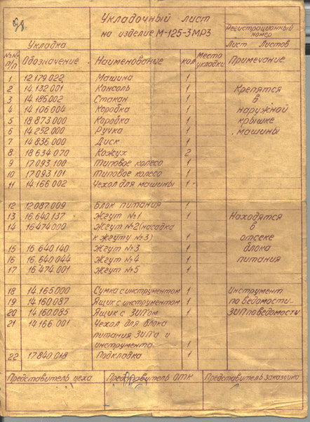
This sheet shows a list of the items that are included with
a model M-125-3MP3 fialka.
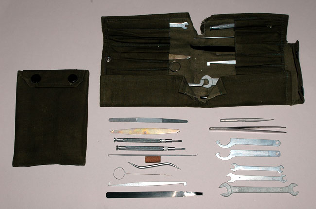
This is the tool kit used for maintenance and adjustment of the Fialka.
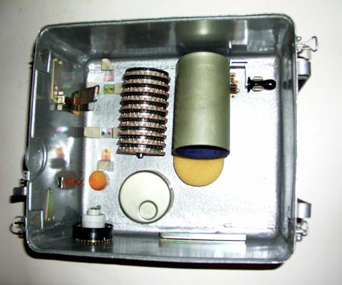
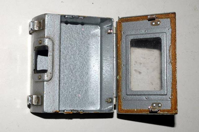
A metal cover protects the Fialka from damage in transit and contains a
variable number of accessories.
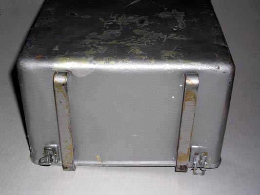
The back of the cover has two metal skids that hold it up.
The inside of the cover may contain accessories as shown. These
accessories may include a hand crank, a special test reflector, additional
print wheels, and a different set of rotors.
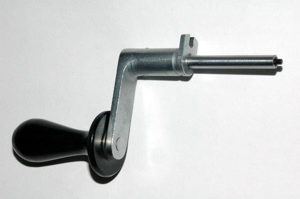
This is the hand crank that may be found inside the cover.
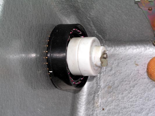
The additional print wheels, if included, are stored inside protective
white plastic covers and stacked on a shaft.
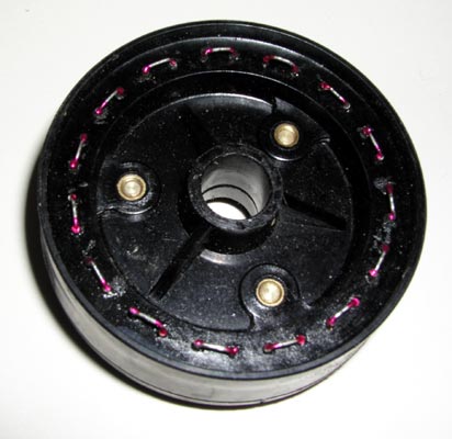
A special black or brown colored TEST REFLECTOR may also be stacked on the
same shaft as shown. To use this test reflector, all rotors are removed from
the rotor shaft, the 'E' clips are installed to hold the test reflector at the
far right end of the shaft, and the shaft is placed in the Fialka. The test
reflector has every pair of adjacent contacts connected together. The
voltages from the Input Wheel are therefore 'reflected' directly back to the
input wheel.
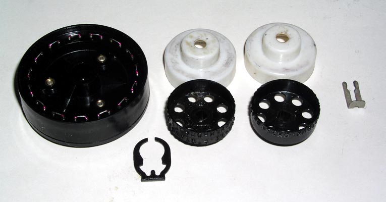
The additional print wheels are shown along with the retaining clips and
the special test reflector after their protective white covers have been
removed.
This is a closer view of the additional print wheels.
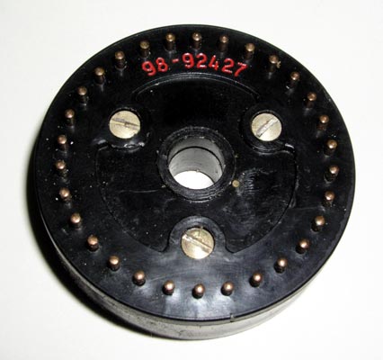
This is a closer view of the input or right side of the special test reflector. These contacts receive voltages from the Input Wheel and reflect them right back to adjacent contacts on the input wheel.
To use this test reflector, all rotors are removed from the rotor shaft, the
'E' clips are installed to hold the test reflector at the far right end of the
shaft, and the shaft is placed in the Fialka. The test reflector has every
pair of adjacent contacts connected together. The voltages from the Input
Wheel are therefore 'reflected' directly back to the input wheel.
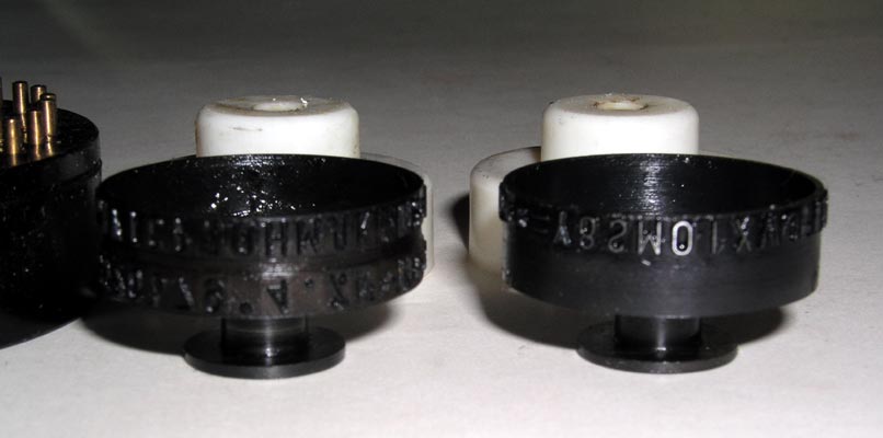
This is a closer view of the left side of the special test reflector.
Notice that adjacent pairs of pins are connected together so that a voltage
coming in on one pin is reflected back out on the adjacent pin.
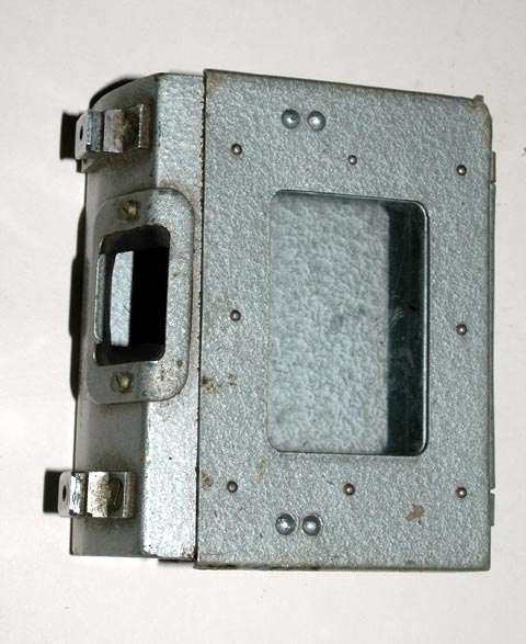
This is the box that catches the paper tape chad (Punched-out pieces of
paper) for the M-125-xxx Fialka.
Another view of the box that catches the paper tape chad for
the M-125-xxx Fialka.
The special Rotor Page describes all sets of rotors in
detail and shows their wiring and stepping data.
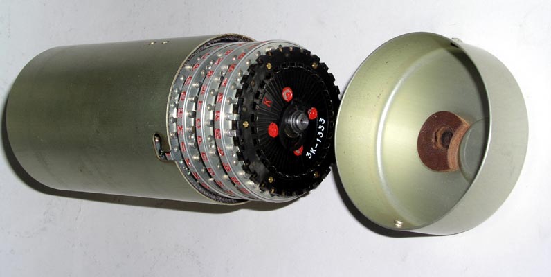
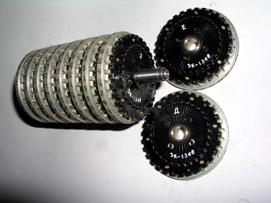
The additional set of rotors, if present, is stored in a protective metal
case.
This is a brief description of the special set of Multi-Adjustable Modular
Wiring Maze rotors. The retaining clip that holds the rotors on the shaft is
shown on the right side of this picture.
(Information on the Non-Adjustable rotor set and wiring and rotation data
for all sets is shown and described in the special detailed
page explaining the rotors:)
PLEASE NOTE:
This is a "3K" series rotor as indicated by the "3K" inscribed on its input
side. These "3K" series rotors are known to have come from Poland.
Another series that has a "6K" inscribed on its input side is known to have
come from the former Czechoslovakia. This suggests the possibility that these
two rotor series were used in different countries or by different military
organizations.
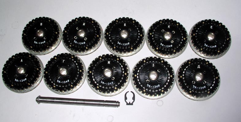
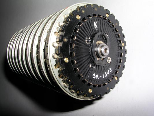
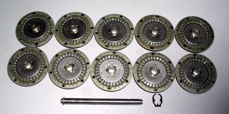
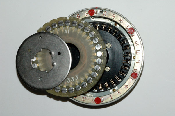
The input contact side of all 10 Multi-Adjustable Modular Wiring Maze
rotors after they have been removed from the shaft.
This photograph shows the special retaining clip location that allows 8 of
the rotors to be mounted on the shaft instead of 10. An accessory spacer
fills in the rest of the rotor stack width.
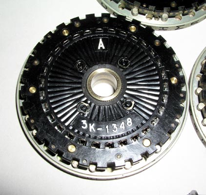
A close view of the input contacts on one of the 10 Multi-Adjustable
Modular Wiring Maze rotors.
The output contact side of all 10 Multi-Adjustable Modular Wiring
Maze rotors after they have been removed from the shaft.
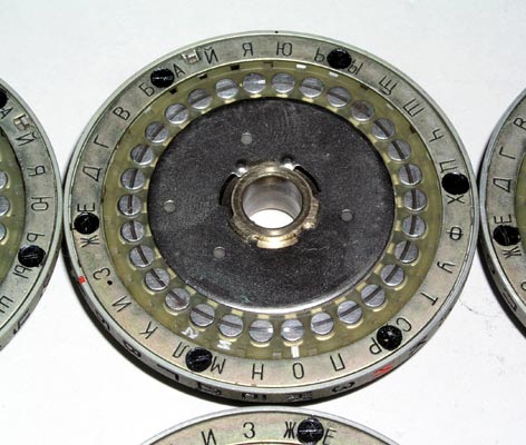
The output contacts on one of the 10 Multi-Adjustable
Modular Wiring Maze rotors.
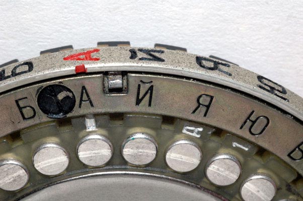
The adjustable outer ring setting on one of the 10 Multi-Adjustable
Modular Wiring Maze rotors. Pushing the pin inwards allows the outer ring to
be rotated to any of the 30 positions.
(The pin can only be pushed inwards AFTER the removable reversible wiring maze
module has been removed.)
The removable reversible wiring maze module is shown being removed from one
of the 10 Multi-Adjustable Modular Wiring Maze rotors. It is removed by
releasing the metal retaining disk. This disk is released by rotating it to
the right or left.
Much more information on rotors, rotor
movement, and the exact internal wiring data is given in: this special rotor description and data page:
NOTE: I AM ALWAYS INTERESTED IN PHOTOGRAPHING OR BUYING VERY UNUSUAL ENIGMA-RELATED MATERIALS, PARTS, EARLY COMPUTERS, AND TELEGRAPH KEYS !
Professor Thomas B. Perera
Montclair State University
COPYRIGHT NOTICE: (Copyright (c) 2005: Prof. Tom Perera Ph. D.)
Although all the pictures and text are copyrighted, you may use any of them
for your own personal applications including public lectures and
demonstrations, publications and websites as long as you mention the
www.w1tp.com/enigma Museum. If you plan to offer them for sale to the public
in any form, you must email me for permission which I will generally grant as
long as you mention my museum: http://w1tp.com/enigma. My email address is
given at the bottom of this page. Some of the material may require contacting
other copyright owners for commercial use and I will inform you by email.
Please also see the disclaimer of warranty.