-
Click BACK to return to the main
Telegraph Web Page.
HOW TO BUILD A SIMPLE WIRELESS TELEGRAPH SET
BACKGROUND AND HISTORY OF TELEGRAPH AND WIRELESS TELEGRAPH:
Ever since the beginnings of time, people have been trying to communicate over distances greater than the human voice could reach. Early attempts included the use of smoke signals, signal fires, waving flags, and the moving arms of semaphores. Mirrors were also used to flash the image of the sun to distant observers.
After the discovery of electricity, wires were stretched from one point to
another and an electric current was either allowed to flow through the wires
or broken by a switch called a telegraph key. The electric current
was first used to make marks on a paper tape and later, it was used activate a
"sounder" which made clicking sounds. The short and long times between
the clicks could be decoded into letters from the alphabet. This type of
telegraph was called land-line telegraph because the wires crossed the
land and used the ground as part of the electric circuit.
This revolutionary discovery allowed people to communicate instantly over
distances that had required days or weeks for horse or train-carried
messages. Telegraph stations were set up along railroads first because the
right-of-way had already been cleared and it was easy to set up poles to carry
the telegraph wires. Railroad dispatchers sent messages via telegraph to
control the movement of trains and the wires also began to carry messages
telling of news events and business transactions. It has been said that the
"electric telegraph" was the most significant invention of the 19th century.
At the very end of the 19th century, it became possible to communicate
by telegraph without using wires. This 'wireless' telegraph system
paved the way for all of today's complex wireless communications systems.
HOW WIRELESS TELEGRAPH WORKS:
Near the end of the 19th century, it was discovered that an
electric spark sent out electrical energy which travelled through
the air without wires and could be detected at a distant point. This
discovery made it possible to communicate without wires.
HOW TO BUILD A SIMPLE WIRELESS TELEGRAPH SET:
The simplest wireless telegraph set consists of a means of
generating and controlling a spark which sends out radio waves into
the air. This is called a transmitter. A complete wireless telegraph set
also requires a receiver or detector to detect the radio waves.
HOW TO BUILD A SIMPLE WIRELESS TELEGRAPH TRANSMITTER:
Probably the simplest way to generate and control a spark is to
use a switch (called a telegraph key) to turn on and off an electromagnetic
buzzer which generates sparks.
The simplest way to receive or detect the radio waves generated by
the buzzer is to use an AM radio tuned to a place on the dial where
there are no other stations.
Here is the simple wireless transmitter which is basically an electrical circuit consisting of 3 parts, all hooked together by wires.
A BATTERY supplies the electricity or voltage.
A KEY is used to complete or break the circuit.
A BUZZER is used to generate the sparks and therefore the radio waves.
(NOTE: This MUST be a buzzer that uses an electromagnet to pull on contacts
and make sparks, It must NOT be an electronic piezo-electric buzzer.
Electromagnetic buzzers are being replaced by piezo-electric buzzers in most
stores so some suggestions about places to find electromagnetic buzzers are
offered below.)
The circuit is shown below: (The lines indicate the wires and the arrowheads show the path of the electrical current as it flows through the wires.)
     !--->---->---->------ BATTERY ---->---->---->-----!
     !              (Supplies the voltage)             !
    KEY                                              BUZZER
    (Completes or breaks                          (Generates sparks
     the electric circuit)                         & radio waves)
     !                                                 !
     !---<----<----<----<----<----<----<----<----<-----!
The WIRES can be virtually any kind of electric wire with the
insulation removed from the ends where the connections are made.
The BATTERY can be flashlight or lantern batteries generating about
4-6-Volts.
The KEY can be any electric switch or a simple piece of metal which
can be bent down to make an electrical contact.
The BUZZER can be an old style door buzzer which used to be sold in hardware
stores. These old buzzers have now has been replaced in most stores by
electronic buzzers that do not make any sparks. They will not work.
Here are some other ways to make or buy an electromagnetic buzzer.
1. You can make a buzzer by removing the bell from an old style doorbell
(which is also becoming a hard thing to find).
2. Although most of the old-time electromagnetic buzzers have been replaced
with electronic circuits that will not generate any sparks and will not work
in this project, you may be able to still find an electromagnetic buzzer
in special science supply companies. Here is one that is current as of
2007:
HobbyTron.com, 1053 South 1675 West, Orem, UT 84058 (800) 494-1778:
www.hobbytron.com/ElectricityKits.html
Catalog number: JA-02014: Electric Bell and Buzzer Kit: $ 7.95
3. Since a buzzer is just an electromagnet which breaks the circuit which
is activating it as soon as it is activated and then makes it again and again,
you can make your own buzzer by winding about 100-200 turns of wire around
a nail and arranging it so that activating this electromagnet pulls
on an armature which opens an electrical contact and breaks the circuit
to the electromagnet. As soon as the circuit is broken, a spring
returns the armiture to it's original position and the circuit
is made again. This cycle of break-the-circuit and make-the-circuit
continues and makes the armature vibrate or buzz for as long
as a voltage is applied. The electric contact makes sparks as it
makes and breaks the circuit. Here is a diagram and some photos showing one
way to make a buzzer.
ELECTRICAL DIAGRAM OF A WIRELESS SPARK TRANSMITER WITH "HOMEMADE" BUZZER:
                                          BUZZER
                                     (Generates Sparks
                                       & Radio Waves)

     !--->----->---->---->---->-------@  Sparking contact on top. (A Nail)
     !                              ~~ \~~   {~SPARKS~}
     !                                   \
     !                                     \    Moveable contact held up by
     !                                       \    its own springiness and
     !                                         \  Pulled down by the coil.
     !                                    !------
    KEY                                   !
    (Completes or breaks       Coil of 100-200 turns of
     the electric circuit)      INSULATED Wire Wrapped
     !                           around an IRON nail
     !                                       !
     !---<----<---- BATTERY ---<----<-----<--!
            (Supplies the voltage)
PHOTOS OF A HOMEMADE BUZZER and WIRELESS SPARK TRANSMITER:
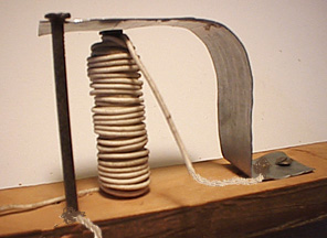 Closeup view of the homemade buzzer. When electricity is applied to the two
wires, the coil around the nail is activated and it pulls DOWN the metal plate
and breaks the circuit {producing a spark}. With the circuit broken, the
metal plate springs back UP and makes the circuit again, causing the coil to
pull it down again and so on. It moves up and down quickly and produces
sparks at it's contacts.
Closeup view of the homemade buzzer. When electricity is applied to the two
wires, the coil around the nail is activated and it pulls DOWN the metal plate
and breaks the circuit {producing a spark}. With the circuit broken, the
metal plate springs back UP and makes the circuit again, causing the coil to
pull it down again and so on. It moves up and down quickly and produces
sparks at it's contacts.
You may have to carefully adjust the metal piece so that it is close enough
to the coil to be pulled down reliably and the location of the contact in
order to get the buzzer to buzz reliably.
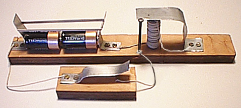 This picture shows the complete wireless spark transmitter with the key,
battery, and buzzer.
This picture shows the complete wireless spark transmitter with the key,
battery, and buzzer.
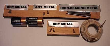 This picture shows the materials you will need if you chose to build this
kind of Wireless Telegraph Transmitter:
This picture shows the materials you will need if you chose to build this
kind of Wireless Telegraph Transmitter:
4. Since a buzzer can be made out of a relay, you could buy a relay from Radio
Shack Company and use it to make a buzzer as follows: The RADIO SHACK
Part Number: 275-240 5VDC/1A SPDT Micro Relay which costs: $ 4.69
will work fine.
Here is how to hook it up: This is the base diagram of the Radio Shack
275-0240 relay when you look directly at the base with the one isolated
contact off to the right. Put the relay in this position:
!========================================================================!
! Pin (Normally Closed)    Pin (Normally open)                           !
!                                                                        !
!                                                                        !
!                                                                        !
! Pin (Coil 1)             Pin (coil 2)                     Pin (Common) !
!========================================================================!
Now: follow these instructions to make it work as a buzzer:
Where it says BUZZER on the diagram of the transmitter above:
Connect the wire from the battery directly to the COIL 2 contact on the
relay.
Connect a wire from the COIL 1 contact on the relay to the Normally Closed
contact (above it).
Connect the other wire (from the key) to the Common contact on the relay.
Now, when you press the key, it will connect the battery to the Common
contact of the relay.
Because the COMMON contact is connected to the coil by way of the Normally
Closed contact and the other side of the coil goes to the battery,
the relay will be activated and it will pull in.
As soon as it pulls in, it's contacts break the circuit and it
will release...
...which will make the circuit and it will pull in
...and then release and pull in and release and so on
...making it into a buzzer.
USING THE WIRELESS TRANSMITTER:
After you have built the transmitter, keying the wireless transmitter
by closing the switch (key) will make the buzzer sparks send out radio waves.
Short key closures are DOTS and long key closures are DASHES.
Combinations of Dots and Dashes are used in the "Morse Code" to
represent letters of the alphabet. For instance, a Dot followed by a
Dash signifies the letter "A".
Here is a link to the two types of codes that were
used to send messages:(2KB)
Try sending your name in Morse Code and see how it sounds. That is how all information
was transmitted in the early 1900s.
You can increase the range of this transmitter somewhat by hooking as long a
single piece of wire as possible onto either contact of the buzzer and using
this wire as an antenna.
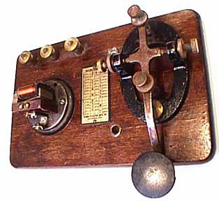
Here is a picture of a commercially-made key and buzzer
telegraph practice set which can also function as a
wireless transmitter. Pressing the key causes the buzzer
to buzz and create sparks which are broadcast through the
air and can be received on an ordinary AM radio.
A key and buzzer practice set like this
can also function as a simple wireless transmitter.
RECEIVING THE SIGNALS: DIFFERENT TYPES OF "DETECTORS"
The simplest detector for your wireless spark transmitter is
a common AM radio tuned to a place on the dial where there are
no other stations. You will hear a noisy stattic sound every time
you press the key. These sounds are exactly like those that people
heard during wireless communications one hundred years ago.
CRYSTAL RADIO SETS:
In the early days of wireless, a crystal made of galena and a pointed piece
of wire called a 'cat's whisker' were brought into contact to make
a simple diode detector. This allowed the radio waves to be
'detected' into DC (Direct Current) electricity which could activate
earphones or headphones. These early radio sets were called
'crystal radio sets'.
CONSTRUCTION OF A CRYSTAL RADIO SET:
You can make a simple crystal radio detector for your wireless
spark transmitter by hooking a wire ANTENNA to a DIODE DETECTOR
and a pair of earphones as shown in the following circuit:
     --->---->---->---WIRE ANTENNA---->---->---->-----!
                 (Picks up the radio waves)           !
                                                    DIODE
                                                   DETECTOR
                                                      !
                                                      !
                                                  EARPHONES
                                                      !
                                                      !
                                     -/-/-/-/-/-/-/-/-/-/-/-/-/-/-/-/-/-
                                     (GROUND: (Bury wire in the ground))
The WIRE should be at least 10 feet long and fairly close to the buzzer.
The DIODE can be almost any diode such as a 1N4001. Diodes can be bought at
Radio Shack Corporation. It doesn't matter
which end is hooked up to the antenna.
The EARPHONES can be almost any sensitive headphones.
The GROUND connection should be a wire, buried in the
(preferably moist) ground.
Keying your spark transmitter should produce a buzzing sound in the
earphones.
If the signal is not strong enough, you might have to attach an
antenna wire to the buzzer contact of your spark transmitter and
put it near the antenna of your receiver.
After it was discovered around 1900 that messages could be sent by radio
waves, the morse code was used to encode those messages. Although voice
communications by radio became possible in the 1920's, the morse code
continues to be used by amateur radio operators to the present. It was only
in the late 1990's that most governments stopped using the code in favor
of voice and satellite communications.
The original "Morse code" (Also called the "American Morse Code")
was used on the land-lines in this country but a
slightly different code called the "Continental" or "International"
code was used in Europe and on the radio waves.
Click here for a comparison of the two
codes:(2KB)
BUILDING A WORKING LAND-LINE TELEGRAPH SYSTEM
If you would like to build a simple working LAND-LINE telegraph set, click on the following link:
How to BUILD a working LAND-LINE telegraph
set:(15KB)
----->> ADDITIONS, CORRECTIONS, and COMMENTS ARE WELCOME ! ! ! ! !
- Click BACK to return to the main Telegraph Web Page.
CONTACT INFORMATION
Please Note: IF YOU DO NOT RECEIVE AN ANSWER TO YOUR EMAIL
IT MEANS THAT I CAN NO LONGER RESPOND.
Please use internet search engines to find other information if you do not receive a reply.
Professor Emeritus:
Montclair State University
- Email Address:
(To help me avoid automated 'junk mail' programs,
I ask you to type my email address as follows with no spaces between words:) - PLEASE TYPE: keys
- THEN TYPE THE @ SYMBOL
- THEN TYPE:
- Please NOTE: { it is w1tp - W then the NUMERAL "1" (one) then tp }... (It is NOT wLtp or wItp).
- Please NOTE: IF YOU DO NOT RECEIVE AN ANSWER TO YOUR EMAIL IT MEANS THAT I CAN NO LONGER RESPOND.
Please use internet search engines to find other information if you do not receive a reply.
- Please NOTE: You MUST include the word KEYS in the Email Subject Line.
- Please Sign your email.
IF you do not receive a reply my spam cleaner might have intercepted your email.
Pease try again with a different Subject and Text.
- ( Please Enquire Before Sending Attachments Larger Than 1MB - Thank you.)
http://w1tp.com
Internet ENIGMA Museum:
https://EnigmaMuseum.com
COPYRIGHT NOTICE: (Copyright (c) 2023: Prof. Tom Perera Ph. D.)
Although all the pictures and text are copyrighted, you may use any of them
for your own personal applications including public lectures and
demonstrations, publications and websites as long as you mention the
w1tp.com Museum. If you plan to offer them for sale to the public
in any form, please email me for permission which I will generally grant as
long as you mention my museum: http://w1tp.com or https://EnigmaMuseum.com My email address is
given at the bottom of this page. Some of the material may require contacting
other copyright owners for commercial use and I will inform you by email.
Please also see the Disclaimer of Warranty.