- Click BACK to return to the main Telegraph Web Page.
HOW TO BUILD SIMPLE TELEGRAPH SETS.
The Electric Telegraph is one of the most important inventions in the history
of science ! It directly led the way to the development of all digital
communications including computers, fax, the internet, email, and text
messaging.
I am often asked for help in building a working electric telegraph set for use
in school projects, science fairs, displays and demonstrations.
I have tried to outline the process of building a simple telegraph set in the
paragraphs below and I have included several variations as well as a simple
wireless telegraph set.
Before you start to build a telegraph set, I STRONGLY SUGGEST that you read
HOW A TELEGRAPH SET WORKS.
This LINK describes the THEORY and OPERATION of the
"electric telegraph".(4KB)
BUILDING A WORKING TELEGRAPH SYSTEM
Many people have inquired about how to build a simple telegraph system to approximate the early systems used in the 19th century. You can view thousands of pictures of telegraph sets in my main telegraph museum: http://w1tp.comHere is a photo of one homemade key and sounder that was build to look just like some of the telegraph sets that were used from 1844 to the 1950s:
As you can see, this was a carefully thought-out and executed project.
Many people just want to build a very simple set to become familiar
with the basic principles of the electric telegraph.
The following project is the simplest functional telegraph system
construction project that I could design. It requires very few
parts and all of them should be commonly available.
 The project uses readily available parts:
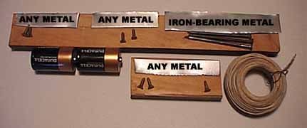
PARTS LIST:
- 2 Pieces of wood. (Any kind of wood will do fine.)
- 9 Small wood screws or nails.
-
2 Large IRON nails.(About 2-3 inches long.)
(NOTE: It is important that these be IRON or STEEL nails. Aluminum and copper nails will not work.)
(You can test these nails to be sure that they are Iron or Steel by making sure that a magnet is attracted to them or by holding a magnetic compass against them to see if it deflects the compass needle.)
-
4 Flat strips of bendable metal.
Three of them should be about 4 inches long.
One should be about 7 inches long.
The long one MUST be iron-bearing or so-called "ferrous" metal which is metal that is attracted by a magnet.
(This kind of metal is often found in some food cans.)
(Be careful not to cut yourself as you cut the strips of metal !)
(You can test this metal strip to be sure that it is ferrous by making sure that a magnet is attracted to it or by holding a magnetic compass against it to see if it deflects the compass needle.
-
20 ft or more of INSULATED solid electrical wire.
(22 - 30 gauge.... (the metal part of the wire should be about 1/64 inch or less in diameter.)
(Radio Shack sells appropriate wire as part number: 278-1345, 278-1215, or 278-502 for about $4.00 ) - 2 Flashlight batteries. (The "D" Cells shown work best.)
(The MORE turns of wire you can wind around the nail, the stronger its magnetism will be and the better it will work.)
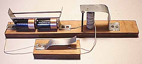
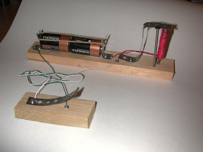
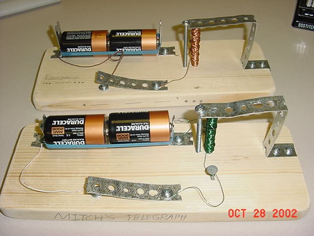
CONSTRUCTION:
Construction of the telegraph set is very simple. Just look at the photographs and you will see how it is put together.
BE CAREFUL NOT
TO CUT YOURSELF ON THE EDGES OF THE METAL STRIPS.
If children will be using the set, you will want to round all sharp corners
with a file or sandpaper and perhaps put tape over any exposed sharp edges.
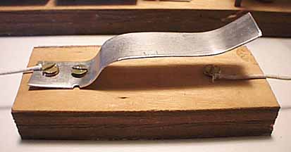 The key is made by screwing one of
the strips of metal to one of the pieces of wood so that pushing
down on the strip brings the strip into electrical contact with the
screw that is mounted under it.
The key is made by screwing one of
the strips of metal to one of the pieces of wood so that pushing
down on the strip brings the strip into electrical contact with the
screw that is mounted under it.
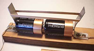 The Battery Holder: is made by
screwing two of the metal strips to the wood so that they
can make electrical contact with each end of the lineup of
the two batteries. A rubber-band may be used to maintain pressure
on the battery contacts.,br>
The Battery Holder: is made by
screwing two of the metal strips to the wood so that they
can make electrical contact with each end of the lineup of
the two batteries. A rubber-band may be used to maintain pressure
on the battery contacts.,br>
Be sure to put the batteries in the holder with the positive tip of one
battery pushing against the negative bottom of the other battery. This is
called a "series connection" of the batteries and adds the 1.5 volt voltage of
one battery to the 1.5 volt voltage of the other battery to produce a total of
3 volts. Most flashlights are designed this way.
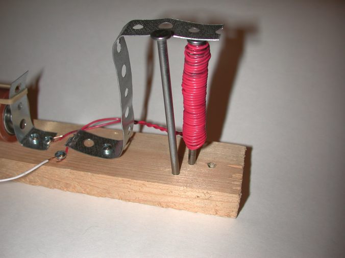
 The Sounder: requires a bit of care
in construction and adjustment.
The Sounder: requires a bit of care
in construction and adjustment.
The electromagnet coil consists of one of the iron nails with
at least 100 turns of the wire wound neatly around it.
( If possible wind on 200 or more turns to make the magnetic
force stronger. )
The longer iron-bearing strip of metal is screwed to the wooden
base and bent so that it extends up and over the top of the nail.
This piece has been labeled "IRON-BEARING" in the parts photograph
to indicate that it is pulled in by the magnet. Many food cans are made
of this type of metal. Be careful not to cut yourself on any
sharp edges.
When the electric current passes through the coil of wire, it
makes the nail into an electromagnet which pulls the strip of
metal down to the nail and makes a clicking sound. (You may
have to carefully adjust the strip of metal so it is close
enough to the nail allow it to be pulled down by the magnet.)
The second nail is important because it keeps the strip of
metal from pulling too far away from the electromagnet.
It also serves to make a clicking sound when the strip
of metal is released by the magnet and moves upward.
To complete the telegraph set, simply connect the key, batteries, and sounder
with the wires as shown in the first picture.
SAFETY NOTE:
When the coil is deenergized by opening the telegraph key, some stored
electricity is released.
It is possible to receive an electric shock if you
are touching both of the contacts of the key with your fingers while you
release the key.
(This can not happen if you build the telegraph key as shown in the
pictures because the bottom contact can not be touched while pressing the key
down.)
There are two ways to eliminate this problem:
1. Make it impossible to touch the lower contact of the key.
The key in the pictures has a lower contact that is covered by the top contact
and it is not possible to touch it at the same time that the top of the key is
being pressed.
2. Place a diode between the two contacts on the key. Radio Shack sells a
diode that will absorb the electricity when the key is released. The Radio
Shack part numbers for appropriate diodes are: 276-1101, 276-1102, 276-1102
or 276-1104 and they cost about $ 1.00.
Just connect the two wires of the diode to the two contacts on
the telegraph key with the white band on the diode being connected to the
side of the key that is connected to the positive (+) side of the battery.
If you have connected the diode incorrectly, opening the key will not open
the circuit. In that case, simply reverse the diode connections.
OPERATION OF THE TELEGRAPH SET:
When you push down on the telegraph key it completes the electrical circuit from the key to one end of the coil and from the other end of the coil to one end of the battery and from the other terminal of the battery back to the other side of the key.Now the sounder magnet should pull down the metal strip and make a CLICKING sound. When you release the key, the metal strip should spring upwards and make a CLACKING sound.
(If it does not work, please see the "Troublshooting section below.)
You can learn to tell the difference between the dots and the
dashes of the Morse code by learning to tell the difference
between the pull-in "CLICK" and the release-"CLACK".
The pull-in "CLICK" is the sound the metal strip makes when
it is pulled in by the electromagnet coil and strikes the
nail which is in the center of the coil.
The release "CLACK" is the sound that the metal strip makes when
it is no longer pulled by the electromagnet coil and it
moves rapidly upward to strike the upper nail.
The Morse Code Characters are called DOTS (or 'dits') and DASHES (or
'dahs') They are made from the CLICKS and CLACKS as follows:
A DOT is created when there is just a LITTLE time between the pull-in CLICK
and the release CLACK.
Try it now: Push the key and quickly release it.
Did you hear the CLICK followed quickly by the CLACK ?
That was a DOT in Morse code.
A DASH is created when there is a LONGER time between the pull-in CLICK
and the release CLACK.
Try it now: Push the key and after a short wait, release it.
Did you hear the CLICK followed after a short wait by the CLACK ?
That was a DASH in Morse code.
Now let's send the letter "A".
In Morse Code, the letter "A" is: DOT DASH. (or Dit Dah).
Push down the key and release it quickly to make a DOT and then push down the
key, wait a bit, and release it to make a DASH.
Try it! You have just sent the Morse Code letter "A".
Now let's send your name in Morse Code:
Find the letters in your name in this Morse Code table that shows the dot and
dash equivalents of letters and numbers in the American Morse Code and the
International code:
http://w1tp.com/percode.htm
(The American Morse Code was mostly used by the railroads and the
International code was used for wireless and radiotelegraphy and in foreign
lands.)
TELEGRAPH SETS BUILT BY OTHER PEOPLE:
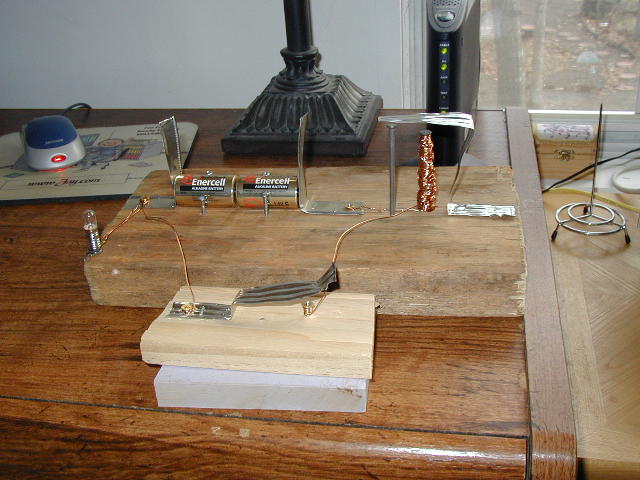
 Here is another version of this set:
It was made by 13 year-old Claire Berry in KwaZulu-Natal, South Africa.
It won a high grade in a science project.
 Here is another version of this set:
 This is a closeup view of the sounder:
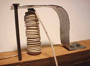
 Here is a third version of this set:
 ***!!DO NOT MAKE A TELEGRAPH SET LIKE THIS ONE !!!
This young builder has made the set with wire that has NO INSULATION on it.
Each turn of the coil short-circuits to every other turn on the coil so the
magnet does not work at all. Please use WELL INSULATED WIRE when you wind the
coil.
***!!DO NOT MAKE A TELEGRAPH SET LIKE THIS ONE !!!
This young builder has made the set with wire that has NO INSULATION on it.
Each turn of the coil short-circuits to every other turn on the coil so the
magnet does not work at all. Please use WELL INSULATED WIRE when you wind the
coil.
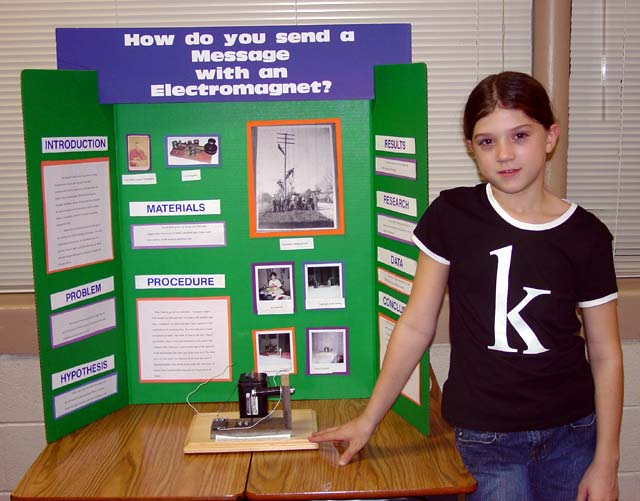 Here is an excellent Telegraph Science Project by 5th.
Grader Katie:
Here is an excellent Telegraph Science Project by 5th.
Grader Katie:
 Here is an American 5th. grade student named Jasiah and the science fair
project that won him first place in his school's Science Fair. He will be
entering it in the County Science Fair in the Spring of 2015:
Here is an American 5th. grade student named Jasiah and the science fair
project that won him first place in his school's Science Fair. He will be
entering it in the County Science Fair in the Spring of 2015:
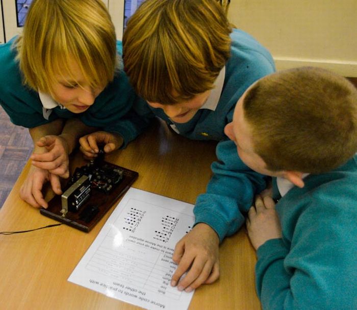 Here are three students practicing with their homemade telegraph set at a
school in England:
Here are three students practicing with their homemade telegraph set at a
school in England:
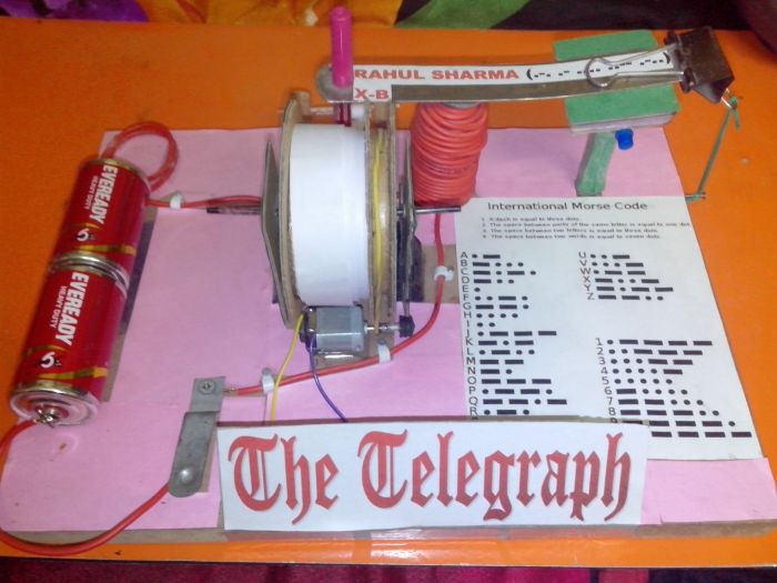
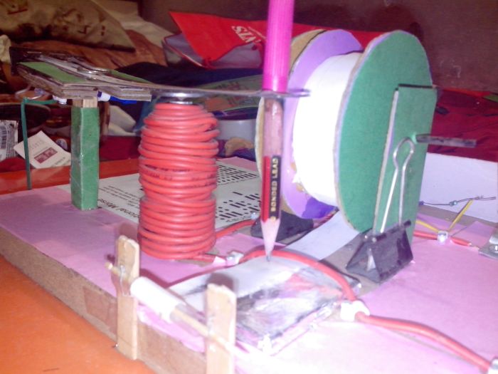
An Excellent Modification of my Basic Design by Rahul Sharma:
15 year-old Rahul Sharma in India designed and constructed a system that uses
a pencil to write dots and dashes on an electric motor-driven moving paper
tape. This makes it easier to read the Morse Coded letters visually and does
not require training in listening to a sounder. He recreated the very first
method of recording the Morse code message on a paper tape as it was invented
and used by Alfred Vail and Samual Morse. He writes: "I modified your design a
little. Instead of a metal strip I made something like a see-saw with ice
cream sticks and mounted a metal scale on it. It was much more difficult to
make but it gave better results. Also, I installed a register to copy down
the code." Here is a picture of Rahul's telegraph set: Nice job, Rahul...

NOTES:
You may use up to 100 feet of wire between the key and the sounder.
Please be careful not to hurt yourself while building this set.
The improper use of tools during construction can cause serious
injury. The original designer of the set and the maintainer of this web
page accept no liability for injuries caused by the construction
or operation of the set.
Here is the circuit diagram of the completed telegraph set:
The components are all in what is called a 'series circuit'.
When the key is closed, the electricity flows in 'series'
from the batteries through the closed key to the sounder and
through the sounder coil back to the other terminal on the batteries.
(The 2 batteries are combined
     !-----KEY-----!
     !             !
     !          BATTERY 1
  SOUNDER       BATTERY 2
     !             !
     !-------------!

And Here is one of the circuits which will allow two of these sets
to be hooked together to send messages to a distant friend. You may
use up to about 100 feet of wire to connect to the other set:

This is the circuit which was used in the early land-line telegraph
stations.  Please NOTE that ONE KEY must be in the 'closed' position
in order for the other key to operate the sounders.  Most of the
early keys had a built-in shorting switch to keep the key circuit
closed and make it possible to receive messages.  One advantage of
this circuit is that the battery can be at either end of the wire
or even in the middle.

                        Wires to other set:
     !------KEY------X.......BATTERY........X-----KEY-----!
     !                                                    !
  SOUNDER                                              SOUNDER
     !    SET 1.                                 Set 2.   !
     !---------------X......................X-------------!
                        Wires to other set:

*** NOTE: ONE key MUST be kept CLOSED in order for the other to work. ***


Here is another circuit which was designed by Bill Horne, W1AC.
The advantage of this circuit is that it allows either key
to operate the sounders at any time without wearing down the batteries and
without the need to close the circuit closing switches on the keys.

NOTE: For this circuit to work, It IS IMPORTANT to wire the batteries with
the POSITIVE (+) and NEGATIVE (-) Terminals as shown.
If you do not do this, the sounders will close as soon
as they are connected.
NOTE: It is also IMPORTANT to use the same voltage..
( ..for example, 2 D-cell batteries.. ) for each battery.

                        Wires to other set:
     !----SOUNDER----!......................!----SOUNDER----!
   + ! +             !                      !             + ! +
  BATTERY           KEY                    KEY           BATTERY
   - ! -  SET 1.     !                      !    Set 2.   - ! -
     !---------------!......................!---------------!
                        Wires to other set:

*** BE SURE THE (+) and (-) BATTERY TERMINALS ARE WIRED AS SHOWN ***
TROUBLESHOOTING PROBLEMS AND SOLUTIONS
Overheating and dead batteries {CAUSED BY USING UNINSULATED WIRES)
One parent emailed that all his completed set did was to have the coil of wire get very hot and that the batteries
went dead shortly afterwards.
After asking him a few questions, I found out that he had
wound bare (uninsulated) wire around the nail. I explained
that the coil of wire had to be made from insulated wire so
that the individual turns in the coil did not electrically connect
to each other.
Sticking Sounder Won't release quickly or at all
One parent noted that closing the key caused the electromagnet
to attract the metal armiture of the sounder but that it did
not release after the circuit was opened.
I suggested increasing the strength of the springiness
of the metal that pulled the armiture away from the nail...
..... AND
INSERTING a very thin piece of plastic sheeting or wrapping materal
between the nail and the armiture to prevent the metal
armiture from directly coming into contact with the nail.
Can't tell the differece between a CLICK and a CLACK
Try using a different metal nail as the upper 'stop'.
Try putting a bit of aluminum foil on the upper stop to change the sound of the release CLACK.
MODIFICATIONS AND ADDITIONS:
There are many ways that you can modify this basic circuit.
For instance, you could put a flashlight bulb or a 3-volt sounder or buzzer in
the series circuit so it would flash or buzz in addition to clicking when you
close the key.
This might help some people to learn to copy the Morse Code more easily.
You could also mount a pencil on the sounder arm and have it mark a piece of paper with either a high mark or a low mark while the paper was pulled under the pencil at an approximately constant speed. This would work exactly like Samual Morse's very first telegraph systems that were used before people learned to copy the Morse Code by ear. Morse invented what he called a "register" which used a clockwork mechanism to pull a paper tape under a pencil which was moved in and out by an electromagnet.
If you use this system it is quite easy to translate the short or long
downwards pencil marks on the paper into dots and dashes. Registers were used
to make Morse Code marks on paper tape right up to the time of the American
Civil war when people finally discvered they could copy Morse Code by ear.
President Abraham Lincoln had a telegraph office that kept him informed of
the progress of the Civil War by receiving telegraph messages from his
generals in the fields of battle.
Good Luck with your projects...
HOW THE TELEGRAPH WORKS:
Explanation of how the telegraph works:BUILDING A WORKING 'WIRELESS' TELEGRAPH SET:
Please click on the following link if you would like to build:A simple working wireless telegraph set:(15KB)
A CIRCUIT FOR OPERATING AN OLD SOUNDER FROM AUDIO TONES:
If you already have an old telegraph sounder and would like to have it operate in response to audio tones such as those from a code practice oscillator or short wave receiver, you will find a simple circuit diagram at this link:A simple circuit for driving a telegraph sounder from audio tones:(20KB)
----->> ADDITIONS, CORRECTIONS, and COMMENTS ARE WELCOME ! ! ! ! !
- Click BACK to return to the main Telegraph Web Page.
CONTACT INFORMATION
Please Note: IF YOU DO NOT RECEIVE AN ANSWER TO YOUR EMAIL
IT MEANS THAT I CAN NO LONGER RESPOND.
Please use internet search engines to find other information if you do not receive a reply.
Professor Emeritus:
Montclair State University
- Email Address:
(To help me avoid automated 'junk mail' programs,
I ask you to type my email address as follows with no spaces between words:) - PLEASE TYPE: keys
- THEN TYPE THE @ SYMBOL
- THEN TYPE:
- Please NOTE: { it is w1tp - W then the NUMERAL "1" (one) then tp }... (It is NOT wLtp or wItp).
- Please NOTE: IF YOU DO NOT RECEIVE AN ANSWER TO YOUR EMAIL IT MEANS THAT I CAN NO LONGER RESPOND.
Please use internet search engines to find other information if you do not receive a reply.
- Please NOTE: You MUST include the word KEYS in the Email Subject Line.
- Please Sign your email.
IF you do not receive a reply my spam cleaner might have intercepted your email.
Pease try again with a different Subject and Text.
- ( Please Enquire Before Sending Attachments Larger Than 1MB - Thank you.)
http://w1tp.com
Internet ENIGMA Museum:
https://EnigmaMuseum.com
COPYRIGHT NOTICE: (Copyright (c) 2023: Prof. Tom Perera Ph. D.)
Although all the pictures and text are copyrighted, you may use any of them
for your own personal applications including public lectures and
demonstrations, publications and websites as long as you mention the
w1tp.com Museum. If you plan to offer them for sale to the public
in any form, please email me for permission which I will generally grant as
long as you mention my museum: http://w1tp.com or https://EnigmaMuseum.com My email address is
given at the bottom of this page. Some of the material may require contacting
other copyright owners for commercial use and I will inform you by email.
Please also see the Disclaimer of Warranty.